


1. Introduction to UML
What is UML?
UML is a powerful tool for software developers, architects, and designers as it provides a common language and notation for communicating design decisions and system architecture. It includes many types of diagrams, such as use case diagrams, class diagrams, and sequence diagrams, that can be used throughout the software development life cycle. UML also supports advanced concepts such as stereotypes, profiles, constraints, and packages, which allow for more precise and tailored modeling of software systems. Overall, UML is a valuable tool for software development and can help to improve communication, collaboration, and the overall quality of software systems.
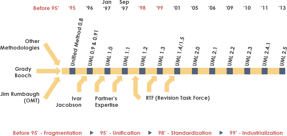
Brief history of UML
UML was first introduced in 1997 as version 1.0, which included nine different types of diagrams. Over the years, new versions of UML were released with additional features and improvements. UML 2.0 was released in 2005, which introduced new diagram types and other enhancements. UML 2.5.1 is the latest version, which was released in 2017 and includes refinements to the language and new features for modeling complex systems. Throughout its history, UML has become widely adopted by software developers and has played a significant role in software development processes.
Why use UML in software development?
UML provides a standardized way to visualize, design, and communicate software systems. It helps to reduce ambiguity, improve collaboration, and increase the efficiency of the software development process.
There are several reasons why UML is widely used in software development:
- Standardization: UML provides a standard visual language and notation for describing software systems. This makes it easier for different stakeholders to understand and communicate design decisions and system architecture.
- Clarity: UML diagrams can help to reduce ambiguity by providing a clear and concise representation of software systems. This can help to prevent misunderstandings and errors during the software development process.
- Collaboration: UML diagrams can be used to facilitate communication and collaboration between different stakeholders, such as developers, architects, and project managers. This can help to ensure that everyone is on the same page and working towards a common goal.
- Efficiency: UML diagrams can help to streamline the software development process by providing a visual representation of software systems that can be used to identify potential issues and design flaws early on.
- Reusability: UML diagrams can be used to document software systems and design patterns, which can be reused in future projects. This can help to save time and resources during the software development process.
Overall, UML is a valuable tool for software development and can help to improve the quality, efficiency, and collaboration of software development projects.
2. UML Diagrams
Types of UML diagrams
UML has many types of diagrams, each with a specific purpose. Some of the most common and more frequently types used include:
- Use case diagrams: illustrate the interactions between a system and its actors.
- Class diagrams: show the structure of a system by modeling its classes, attributes, and relationships.
- Object diagrams: depict instances of classes in a system.
- Sequence diagrams: describe the interactions between objects in a system over time.
- Collaboration diagrams: similar to sequence diagrams but focus on the relationships between objects.
- Statechart diagrams: model the behavior of objects in response to events.
- Activity diagrams: show the flow of activities within a system.
- Component diagrams: illustrate the organization and dependencies of system components.
- Deployment diagrams: show the physical arrangement of hardware and software components in a system.
Use case diagrams
Use case diagrams are a type of UML diagram that are used to model the functionality of a system and its interactions with external actors. They are particularly useful for identifying the boundaries of a system and the requirements for its functionality.
Use case diagrams consist of actors, use cases, and the relationships between them. Actors are external entities, such as users, customers, or other systems, that interact with the system being modeled. Use cases represent the functionality of the system, such as a specific task or process that can be performed by the system.
The relationships between actors and use cases are represented by lines connecting them. There are several types of relationships that can be used in a use case diagram, including:
- Association: A basic relationship between an actor and a use case, indicating that the actor can perform the use case.
- Extend: A relationship indicating that a use case can be extended by another use case. This is typically used to represent optional functionality.
- Include: A relationship indicating that a use case includes another use case. This is typically used to represent common functionality that is used by multiple use cases.
- Generalization: A relationship indicating that a more specific use case is a specialization of a more general use case.
Use case diagrams can be used to identify the functional requirements of a system and to ensure that all necessary functionality is included in the design. They can also be used to communicate the functionality of a system to stakeholders and to ensure that everyone is on the same page regarding the requirements of the system. Overall, use case diagrams are a valuable tool for software development and can help to ensure that the functionality of a system is well-defined and clearly understood.
Class diagrams
Class diagrams are a type of UML diagram that are used to model the structure of a system by defining its classes, attributes, and relationships. They are particularly useful for representing object-oriented designs and can help to identify inheritance hierarchies and class responsibilities.
Class diagrams consist of classes, attributes, and relationships between classes. Classes represent the objects in the system being modeled, and attributes represent the properties of those objects. Relationships between classes are represented by lines connecting them, and there are several types of relationships that can be used in a class diagram, including:
- Association: A basic relationship between two classes, indicating that they are related in some way.
- Aggregation: A relationship indicating that one class contains another class as a part. For example, a car contains an engine.
- Composition: A stronger form of aggregation indicating that one class is a part of another class and cannot exist without it. For example, a car cannot exist without an engine.
- Inheritance: A relationship indicating that one class is a subclass of another class, inheriting its attributes and methods.
Class diagrams can be used to identify the structure of a system and to ensure that the classes and relationships between them are well-defined and clearly understood. They can also be used to generate code from the design and to ensure that the implementation of the system follows the design. Overall, class diagrams are a valuable tool for software development and can help to ensure that the structure of a system is well-designed and easy to understand.
Object diagrams
Object diagrams consist of objects, attributes, and relationships between objects. Objects represent instances of classes, and attributes represent the values of those objects. Like class diagram, relationships between objects are represented by lines connecting them, and there are several types of relationships that can be used in an object diagram, including:
- Association: A relationship between two objects, indicating that they are related in some way.
- Aggregation: A relationship indicating that one object contains another object as a part.
- Composition: A stronger form of aggregation indicating that one object is a part of another object and cannot exist without it.
Object diagrams can be used to test the validity of a class diagram by instantiating classes and verifying that their relationships and attributes are correctly defined. They can also be used to model specific scenarios within a system, such as the state of objects at a particular point in time. Object diagrams are particularly useful for testing and debugging object-oriented systems, as they allow developers to visualize the behavior of objects and their relationships in real-time.
Overall, object diagrams are a valuable tool for software development and can help to ensure that the behavior of a system is well-defined and well-understood. They are especially useful for testing and debugging object-oriented systems and for modeling specific scenarios within a system.
Sequence diagrams
Sequence diagrams are a type of UML diagram that describe the interactions between objects in a system over time. They can be used to model the behavior of a system, especially in response to user input or external events.
Sequence diagrams consist of objects, messages, and lifelines. Objects represent instances of classes, and lifelines represent the lifespan of an object during the sequence. Messages represent the interactions between objects, and there are several types of messages that can be used in a sequence diagram, including:
- Synchronous messages: Messages that require a response before the sequence can continue.
- Asynchronous messages: Messages that do not require an immediate response and allow the sequence to continue.
- Return messages: Messages that represent the return value of a synchronous message.
Sequence diagrams can be used to model the behavior of a system by depicting the sequence of interactions between objects in response to user input or external events. They are particularly useful for understanding how a system behaves under different scenarios and for identifying potential issues or inefficiencies in the system design.
Overall, sequence diagrams are a valuable tool for software development and can help to ensure that the behavior of a system is well-understood and well-designed. They are especially useful for modeling the interactions between objects in response to user input or external events.
Collaboration diagrams
Collaboration diagrams, also known as communication diagrams, are similar to sequence diagrams in that they describe the interactions between objects in a system. However, while sequence diagrams focus on the order of interactions, collaboration diagrams emphasize the relationships between objects.
In a collaboration diagram, objects are represented as boxes, and the relationships between them are depicted as lines. Messages between objects are labeled with the method or operation being called, and there are several types of messages that can be used, including synchronous, asynchronous, and return messages.
Collaboration diagrams can be used to model complex interactions between objects or to highlight communication patterns within a system. They are particularly useful for identifying potential issues or inefficiencies in the system design, as well as for understanding the relationships between objects and how they work together to accomplish a particular task.
Overall, collaboration diagrams are a valuable tool for software development and can help to ensure that the interactions between objects in a system are well-understood and well-designed. They are especially useful for modeling complex systems with many objects and interactions.
Statechart diagrams
Statechart diagrams are a type of UML diagram that model the behavior of objects in response to events. They can be used to show the transitions between different states of an object and to identify the triggers that cause those transitions.
In a statechart diagram, an object is represented as a rectangle, and the states of the object are represented as circles or rounded rectangles. The transitions between states are depicted as arrows, and the triggers for those transitions are labeled on the arrows.
Statechart diagrams can be used to model the behavior of an object in response to different events, such as user input or changes in the system environment. They are particularly useful for identifying the possible states of an object and the transitions between those states, as well as for understanding the triggers for those transitions.
Overall, statechart diagrams are a valuable tool for software development and can help to ensure that the behavior of an object in a system is well-understood and well-designed. They are especially useful for modeling complex systems with many states and transitions.
Activity diagrams
Activity diagrams are a type of UML diagram that show the flow of activities within a system. They can be used to model the logic of a process or to describe the steps involved in a use case.
In an activity diagram, activities are represented as rounded rectangles, and the flow of activities is depicted as arrows. The start and end points of the process are represented by circles or rounded rectangles, and decision points are represented by diamonds.
Activity diagrams can be used to model complex processes or workflows, including business processes or software workflows. They are particularly useful for identifying the steps involved in a particular use case or process and for understanding the flow of activities between those steps.
Overall, activity diagrams are a valuable tool for software development and can help to ensure that the flow of activities within a system is well-understood and well-designed. They are especially useful for modeling complex processes with many steps and decision points.
Component diagrams
Component diagrams are a type of UML diagram that illustrate the organization and dependencies of system components. They can be used to model the structure of a system at a high level and to identify potential areas of reuse.
In a component diagram, components are represented as rectangles with ports that indicate the interfaces through which they interact with other components. The connections between components are depicted as lines, and the dependencies between components are represented by arrows.
Component diagrams can be used to model the architecture of a system and to identify potential areas for reuse of components. They are particularly useful for understanding the relationships between different components of a system and for identifying potential areas of improvement or optimization.
Overall, component diagrams are a valuable tool for software development and can help to ensure that the structure of a system is well-designed and well-organized. They are especially useful for modeling complex systems with many interdependent components.
Deployment diagrams
Deployment diagrams are a type of UML diagram that show the physical arrangement of hardware and software components in a system. They can be used to identify the hardware and software requirements of a system and to plan its deployment.
In a deployment diagram, nodes represent the physical components of the system, such as servers or workstations, and the components deployed on those nodes are represented by rectangles. The connections between nodes are depicted as lines, and the dependencies between components are represented by arrows.
Deployment diagrams can be used to model the deployment of a system and to identify potential issues or constraints that may arise during deployment. They are particularly useful for understanding the physical requirements of a system and for planning the deployment process.
Overall, deployment diagrams are a valuable tool for software development and can help to ensure that the deployment of a system is well-planned and well-executed. They are especially useful for modeling complex systems with many interconnected components and for identifying potential issues that may arise during deployment.
3. Best practices for creating UML diagrams
To create effective UML diagrams, it’s important to follow some best practices, such as:
- Keep the diagrams simple and easy to understand.
- Use consistent notation and naming conventions.
- Use colors and shading to highlight important elements.
- Use meaningful labels for elements and relationships.
- Focus on the most important aspects of the system.
4. Advanced UML Concepts
UML stereotypes
UML stereotypes are custom extensions to the UML notation that allow you to add additional semantics to UML elements. Stereotypes are typically defined using the «stereotype» notation.
For example, you might use a stereotype to indicate that a class represents a specific type of object, such as a controller or a database entity. Stereotypes can also be used to indicate the role that an object plays in a system or to provide additional information about the behavior of a system element.
Stereotypes can be applied to any UML element, including classes, objects, use cases, and components. They can also be used to define custom UML elements that are specific to your system.
UML stereotypes can be a powerful tool for software development, as they allow you to add additional meaning and context to UML diagrams. They can help to clarify the purpose and role of UML elements and can make it easier to understand complex systems. Stereotypes can also help to ensure that UML diagrams are more closely aligned with the needs of your specific project or organization.
UML profiles
UML profiles are collections of stereotypes and other UML extensions that are tailored to a specific domain or application. Profiles can be used to extend UML with domain-specific concepts and notation.
A UML profile consists of a set of stereotypes, tagged values, and constraints that define a specific domain or application. Profiles are typically created using the Unified Profile for Modeling and Integration (UPDM) or the SysML profile for UML.
Profiles can be used to extend UML with new modeling concepts, such as domain-specific classes or components, and to specify custom behavior for existing UML elements. For example, you might use a profile to define a set of stereotypes and constraints for modeling cybersecurity concepts, such as threat actors and vulnerabilities.
Profiles can be applied to UML models to extend their capabilities and provide a more tailored modeling experience. They can also be used to define custom views and perspectives on a UML model, making it easier to navigate and understand complex systems.
Overall, UML profiles are a powerful tool for software development, as they allow you to extend UML with domain-specific concepts and notation. They can help to ensure that UML models are better aligned with the needs of your specific project or organization and can make it easier to understand and communicate complex systems.
UML constraints
UML constraints are logical expressions that constrain the values or relationships of UML elements. Constraints are typically defined using the Object Constraint Language (OCL) notation.
Constraints can be applied to UML elements such as classes, attributes, associations, operations, and parameters, among others. They can be used to specify validation rules for UML models and to ensure that the models conform to specific requirements and standards.
For example, a constraint could be used to specify that the age of a person in a UML class must be greater than zero and less than 150. Another constraint could be used to specify that a UML association between two classes is valid only if the multiplicity of one end is less than or equal to the multiplicity of the other end.
Constraints are important in UML modeling because they help to ensure the correctness and consistency of UML models. By defining constraints, you can specify the expected behavior of UML elements and detect potential errors and inconsistencies early in the modeling process.
Overall, UML constraints are a valuable tool for UML modeling, as they allow you to define validation rules for UML models and ensure that the models conform to specific requirements and standards.
UML packages
UML packages are used to organize UML elements into logical groups. Packages can be used to simplify large UML diagrams and to manage the complexity of large systems. Packages can contain any number of UML elements, including classes, use cases, components, and other packages.
Packages are typically represented as rectangles with a tab at the top, and they can be nested within other packages to create a hierarchical structure. Each package can have a name and a unique identifier, and it can be associated with other packages using dependencies, which indicate that one package depends on another.
Packages can be used to simplify UML diagrams by grouping related elements together and hiding unnecessary details. For example, a package could be used to group all of the classes related to a particular subsystem or module of a system, making it easier to understand the structure and behavior of that subsystem or module.
Packages can also be used to manage the complexity of large systems by dividing the system into smaller, more manageable components. This can make it easier to develop and maintain the system over time, as changes to one package are less likely to affect other packages in the system.
Overall, UML packages are a valuable tool for organizing and managing UML models, as they allow you to group related elements together and manage the complexity of large systems.
5. UML and Software Development
UML in the software development life cycle
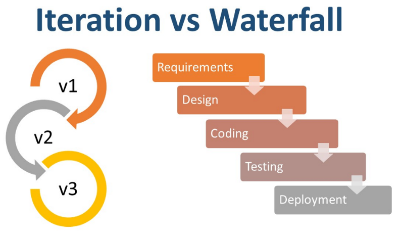
UML can be used throughout the software development life cycle, from requirements gathering to implementation and testing. UML diagrams can help to communicate requirements, design decisions, and system architecture to stakeholders.
Here are some examples of how UML can be used in each stage of the software development life cycle:
- Requirements gathering:
- Use case diagrams can be used to identify and model the functional requirements of the system.
- Activity diagrams can be used to model the steps involved in a use case.
- Analysis and design:
- Class diagrams can be used to model the structure of the system and its objects.
- Sequence diagrams and collaboration diagrams can be used to model the interactions between objects and components.
- Statechart diagrams can be used to model the behavior of objects in response to events.
- Implementation:
- Class diagrams can be used as a blueprint for writing code.
- Component diagrams can be used to identify the components of the system and their dependencies.
- Testing:
- Sequence diagrams and collaboration diagrams can be used to model the interactions between components and to identify potential issues in the system’s behavior.
- Maintenance:
- UML diagrams can be used to document the system and its architecture, making it easier to understand and modify over time.
UML in agile development
UML can be used in agile development to facilitate communication, collaboration, and continuous integration. UML diagrams can be used to capture user stories, design decisions, and sprint backlogs. Here are some ways UML can be used in agile development:
- User story mapping: UML use case diagrams and activity diagrams can be used to map user stories to specific features and activities in a system.
- Sprint planning: UML class and sequence diagrams can be used to visualize the implementation of user stories and to identify potential design issues.
- Continuous integration: UML component and deployment diagrams can be used to identify dependencies between system components and to plan the deployment of system updates.
- Collaboration: UML collaboration and communication diagrams can be used to facilitate communication and collaboration between team members and stakeholders.
Overall, the use of UML in agile development can help to improve communication, promote collaboration, and ensure that the development process is aligned with user needs and system requirements.
UML and design patterns
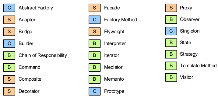
UML can be used to model and document design patterns. Design patterns are reusable solutions to common software design problems. They provide a structured approach to solving design problems and can improve the quality of software systems.
UML diagrams can be used to illustrate the structure and behavior of design patterns. Class diagrams, for example, can be used to model the classes and relationships involved in a design pattern. Sequence diagrams can be used to model the interactions between objects in a design pattern, while statechart diagrams can be used to model the states and transitions of objects.
UML can also help to communicate the implementation of design patterns to developers. By using UML diagrams to model design patterns, developers can understand the structure and behavior of the pattern and how it can be implemented in their code.
In addition, UML profiles can be used to extend UML with domain-specific design patterns. These profiles can provide a standardized notation and vocabulary for communicating and implementing design patterns in specific domains.
6. UML Case Studies
Real-world examples of using UML
UML has been widely used in various industries and projects. Here are some real-world examples of using UML successfully:
- Banking: UML has been used to design and develop banking software systems, such as ATM machines and online banking applications. UML diagrams have been used to model user interfaces, transactions, and security features.
- Healthcare: UML has been used to model electronic health record (EHR) systems, medical devices, and clinical decision support systems. UML diagrams have been used to model patient information, workflows, and interactions between medical professionals and patients.
- Automotive: UML has been used to design and develop software systems for automobiles, such as infotainment systems, navigation systems, and driver assistance systems. UML diagrams have been used to model the interactions between software components and hardware devices.
- Aerospace: UML has been used to design and develop software systems for aerospace applications, such as flight control systems and satellite control systems. UML diagrams have been used to model the behavior of complex systems and to manage the interactions between subsystems.
- Gaming: UML has been used to design and develop video games, such as game engines and game development tools. UML diagrams have been used to model game mechanics, player interactions, and game assets.
These are just a few examples of how UML has been used successfully in real-world projects across various industries.
Analysis of UML in software development projects
UML has been used in many software development projects, both successfully and unsuccessfully. Analyzing these projects can help to identify best practices and pitfalls of using UML in practice.
7. Conclusion
Summary of UML concepts
UML is a powerful visual language for modeling and documenting software systems. It includes many types of diagrams, such as use case diagrams, class diagrams, and sequence diagrams, that can be used throughout the software development life cycle.
UML also includes features such as stereotypes, profiles, and constraints that allow for custom extensions and tailoring to specific domains or applications. UML can be used in agile development processes and can be applied to design patterns to improve software design and development. Proper utilization of UML can help to reduce ambiguity, improve collaboration, and increase the efficiency of the software development process.
Future trends in UML and software development
UML continues to evolve, with new extensions and refinements being added to the language. The future of UML and software development will likely involve greater integration with other development methodologies, such as agile and DevOps.
In addition, there is a growing trend towards model-driven development (MDD), which emphasizes the use of UML and other modeling languages to automatically generate code and reduce development time. There is also a push towards the use of UML in the development of cyber-physical systems, which integrate physical and digital components. Another trend is the use of UML in the development of artificial intelligence and machine learning systems, as these systems become increasingly complex and require more advanced modeling techniques.
Overall, UML will continue to play a key role in software development, as it provides a standardized way to model and communicate software systems.
UML Resources for Beginners
- What is UML?
- Why UML Modeling?
- Overview of the 14 UML Diagram Types
- What is Class Diagram?
- What is Component Diagram?
- What is Deployment Diagram?
- What is Object Diagram?
- What is Package Diagram?
- What is Composite Structure Diagram?
- What is Profile Diagram?
- What is Use Case Diagram?
- What is Activity Diagram?
- What is State Machine Diagram?
- What is Sequence Diagram?
- What is Communication Diagram?
- What is Interaction Overview Diagram?
- What is Timing Diagram
- What is UML Collaboration Diagram?
- UML Association vs Aggregation vs Composition
This post is also available in Deutsch, Español, فارسی, Français, English, Bahasa Indonesia, 日本語, Polski, Portuguese, Ру́сский, Việt Nam, 简体中文 and 繁體中文.