


The Unified Modeling Language (UML) is a general-purpose, developmental modeling language in the field of software engineering, designed to provide a standard approach to visualizing system design. The original motivation for creating UML was the desire to standardize different notation systems and software design methods. In UML, a class diagram is one of six types of structure diagrams. Class diagrams are the basis of the object modeling process and model the static structure of the system.
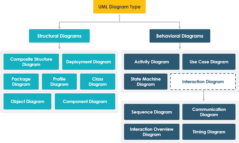
Structure diagrams show the static structure of the system and its parts on different abstraction and implementation levels and how they are related to each other. The elements in a structure diagram represent the meaningful concepts of a system, and may include abstract, real world and implementation concepts, there are seven types of structure diagram as follows:
- Class Diagram
- Component Diagram
- Deployment Diagram
- Object Diagram
- Package Diagram
- Composite Structure Diagram
- Profile Diagram
What is a Class Diagram?
A class diagram in the Unified Modeling Language (UML) is a static structure diagram that describes the structure of a system by showing its classes, their attributes, operations (or methods), and the relationships between objects. A class diagram is a blueprint for a system or subsystem. You can use class diagrams to model the objects that make up the system, show the relationships between objects, and describe the roles of these objects and the services they provide.
The Origin of UML
The goal of UML is to provide a standard notation that can be used by all object-oriented methods and to select and integrate the best elements of precursor notations. UML has been designed for a broad range of applications. Hence, it provides constructs for a broad range of systems and activities (e.g., distributed systems, analysis, system design and deployment).
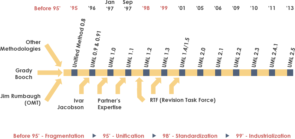
UML is a notation that resulted from the unification of OMT from
- Object Modeling Technique OMT [James Rumbaugh 1991] – was best for analysis and data-intensive information systems.
- Booch [Grady Booch 1994] – was excellent for design and implementation. Grady Booch had worked extensively with the Ada language, and had been a major player in the development of Object Oriented techniques for the language. Although the Booch method was strong, the notation was less well received (lots of cloud shapes dominated his models – not very tidy)
- OOSE (Object-Oriented Software Engineering [Ivar Jacobson 1992]) – featured a model known as Use Cases. Use Cases are a powerful technique for understanding the behaviour of an entire system (an area where OO has traditionally been weak).
In 1994, Jim Rumbaugh, the creator of OMT, stunned the software world when he left General Electric and joined Grady Booch at Rational Corp. The aim of the partnership was to merge their ideas into a single, unified method (the working title for the method was indeed the “Unified Method”).
The Purpose of Class Diagram
Class diagrams are useful in many phases of system design. During the analysis phase, class diagrams can help you understand the requirements of the problem domain and identify its components. In object-oriented software projects, the class diagram created in the early stages of the project contains classes that are often converted into actual software classes and objects when writing code.
Later, you can refine the early analysis and conceptual models into class diagrams to show specific parts of the system, user interfaces, logic implementations, and so on.
Class diagrams are widely used in modeling object-oriented systems because they are the only UML diagrams that can be mapped directly to object-oriented languages. During the implementation phase of the software development cycle, you can use class diagrams to transform models into code and code into models.
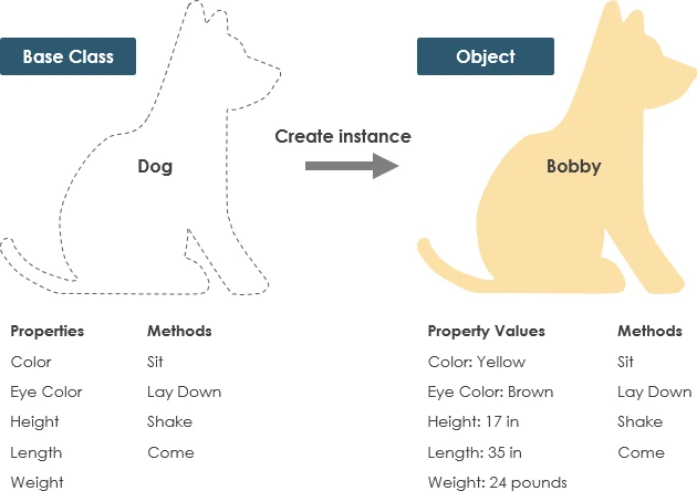
Class Example
A dog has states – color, name, breed as well as behaviors -wagging, barking, eating. An object is an instance of a class.
UML Class Notation
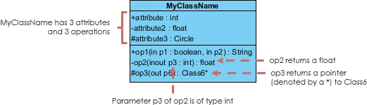
A class represent a concept which encapsulates state (attributes) and behavior (operations). Each attribute has a type. Each operation has a signature. The class name is the only mandatory information.
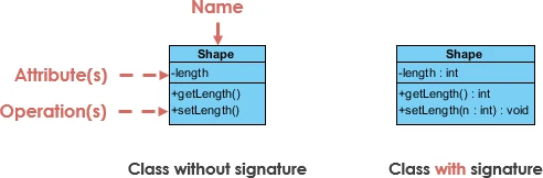
Class Name:
- The name of the class appears in the first partition.
Class Attributes:
- Attributes are shown in the second partition.
- The attribute type is shown after the colon.
- Attributes map onto member variables (data members) in code.
Class Operations (Methods):
- Operations are shown in the third partition. They are services the class provides.
- The return type of a method is shown after the colon at the end of the method signature.
- The return type of method parameters are shown after the colon following the parameter name. Operations map onto class methods in code
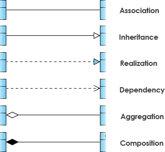
Class Relationships
A class may be involved in one or more relationships with other classes. A relationship can be one of the following types: (Refer to the figure on the right for the graphical representation of relationships).
| Relationship Type | Graphical Representation |
|---|---|
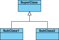
Inheritance (or Generalization):
|
 |
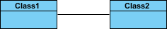
Simple Association:
|
 |
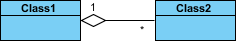
| Aggregation:
A special type of association. It represents a “part of” relationship.
|
 |
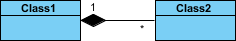
| Composition:
A special type of aggregation where parts are destroyed when the whole is destroyed.
|
 |
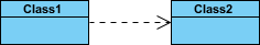
Dependency:
|
 |
Relationship Names
- Names of relationships are written in the middle of the association line.
- Good relation names make sense when you read them out loud:
- “Every spreadsheet contains some number of cells”,
- “an expression evaluates to a value”
- They often have a small arrowhead to show the direction in which direction to read the relationship, e.g., expressions evaluate to values, but values do not evaluate to expressions.
Relationship – Roles
- A role is a directional purpose of an association.
- Roles are written at the ends of an association line and describe the purpose played by that class in the relationship.
- E.g., A cell is related to an expression. The nature of the relationship is that the expression is the formula of the cell.
Visibility of Class attributes and Operations
In object-oriented design, there is a notation of visibility for attributes and operations. UML identifies four types of visibility: public, protected, private, and package.
The +, -, # and ~ symbols before an attribute and operation name in a class denote the visibility of the attribute and operation.
- + denotes public attributes or operations
- – denotes private attributes or operations
- # denotes protected attributes or operations
- ~ denotes package attributes or operations
Class Visibility Example
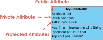
In the example above:
- attribute1 and op1 of MyClassName are public
- attribute3 and op3 are protected.
- attribute2 and op2 are private.
Access for each of these visibility types is shown below for members of different classes.
| Access Right | public (+) | private (-) | protected (#) | Package (~) |
|---|---|---|---|---|
| Members of the same class | yes | yes | yes | yes |
| Members of derived classes | yes | no | yes | yes |
| Members of any other class | yes | no | no | in same package |
Multiplicity
How many objects of each class take part in the relationships and multiplicity can be expressed as:
- Exactly one – 1
- Zero or one – 0..1
- Many – 0..* or *
- One or more – 1..*
- Exact Number – e.g. 3..4 or 6
- Or a complex relationship – e.g. 0..1, 3..4, 6.* would mean any number of objects other than 2 or 5
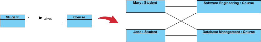
Multiplicity Example
- Requirement: A Student can take many Courses and many Students can be enrolled in one Course.
- In the example below, the class diagram (on the left), describes the statement of the requirement above for the static model while the object diagram (on the right) shows the snapshot (an instance of the class diagram) of the course enrollment for the courses Software Engineering and Database Management respectively)

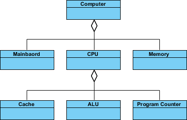
Aggregation Example – Computer and parts
- An aggregation is a special case of association denoting a “consists-of” hierarchy
- The aggregate is the parent class, the components are the children classes
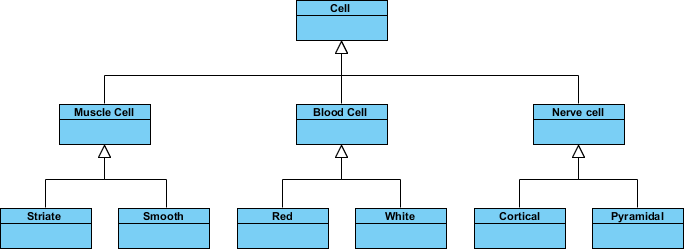
Inheritance Example – Cell Taxonomy
- Inheritance is another special case of an association denoting a “kind-of” hierarchy
- Inheritance simplifies the analysis model by introducing a taxonomy
- The child classes inherit the attributes and operations of the parent class.
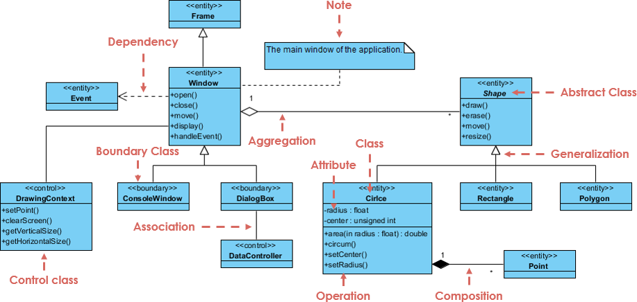
Class Diagram – Diagram Tool Example
A class diagram may also have notes attached to classes or relationships. Notes are shown in grey.

In the example above:
We can interpret the meaning of the above class diagram by reading through the points as following.
- Shape is an abstract class. It is shown in Italics.
- Shape is a superclass. Circle, Rectangle and Polygon are derived from Shape. In other words, a Circle is-a Shape. This is a generalization / inheritance relationship.
- There is an association between DialogBox and DataController.
- Shape is part-of Window. This is an aggregation relationship. Shape can exist without Window.
- Point is part-of Circle. This is a composition relationship. Point cannot exist without a Circle.
- Window is dependent on Event. However, Event is not dependent on Window.
- The attributes of Circle are radius and center. This is an entity class.
- The method names of Circle are area(), circum(), setCenter() and setRadius().
- The parameter radius in Circle is an in parameter of type float.
- The method area() of class Circle returns a value of type double.
- The attributes and method names of Rectangle are hidden. Some other classes in the diagram also have their attributes and method names hidden.
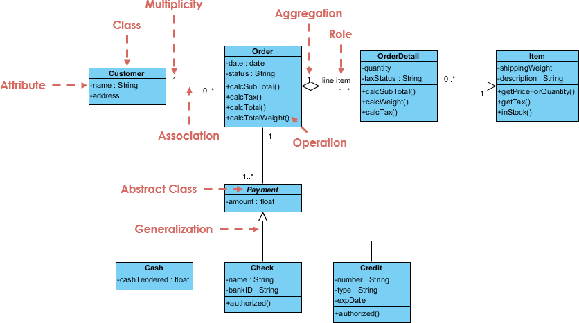
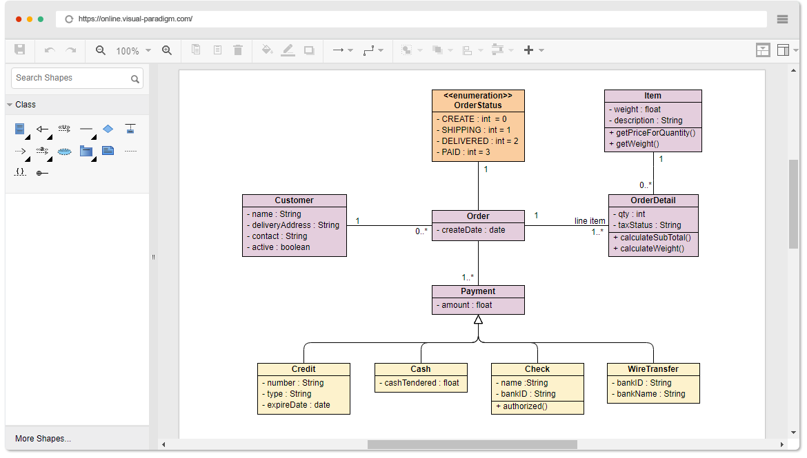
Class Diagram Example: Order System
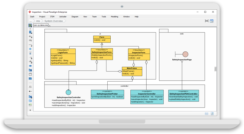
Class Diagram Example: GUI
A class diagram may also have notes attached to classes or relationships.
Dealing with Complex System – Multiple or Single Class Diagram?
Inevitably, if you are modeling a large system or a large business area, there will be numerous entities you must consider. Should we use multiple or a single class diagram for modeling the problem? The answer is:
- Instead of modeling every entity and its relationships on a single class diagram, it is better to use multiple class diagrams.
- Dividing a system into multiple class diagrams makes the system easier to understand, especially if each diagram is a graphical representation of a specific part of the system.
Perspectives of Class Diagram in Software Development Lifecycle
We can use class diagrams in different development phases of a software development lifecycle and typically by modeling class diagrams in three different perspectives (levels of detail) progressively as we move forward:
Conceptual perspective: The diagrams are interpreted as describing things in the real world. Thus, if you take the conceptual perspective you draw a diagram that represents the concepts in the domain under study. These concepts will naturally relate to the classes that implement them. The conceptual perspective is considered language-independent.
Specification perspective: The diagrams are interpreted as describing software abstractions or components with specifications and interfaces but with no commitment to a particular implementation. Thus, if you take the specification perspective we are looking at the interfaces of the software, not the implementation.
Implementation perspective: The diagrams are interpreted as describing software implementations in a particular technology and language. Thus, if you take the implementation perspective we are looking at the software implementation.
Looking for a free class diagramming tool?
Visual Paradigm Online (VP Online) Free Edition is a free online drawing software that supports class diagrams, other UML diagrams, ERD tools and organization chart tools. It has a simple yet powerful editor that allows you to create class diagrams quickly and easily. This free UML editor has no ads, no access deadlines, and no restrictions, for example, on the number of diagrams, the number of shapes, etc. You own the diagrams you create for personal and non-commercial purposes.
Looking for more formal UML modeling on your desktop ?
Visual Paradigm Community Edition was launched since 2004 to provide a free UML software for sole non-commercial purpose, supporting users who was making their first steps in UML modeling, and who need a free and cross-platform UML modelling software for personal use, such as applying UML on student projects.
UML modelling tool free for all sorts of non-commercial purpose. Supporting the 13 UML 2.x diagrams

We are adopted by over 1 Million installations around the globe, and is still growing. Many people are using the paid editions of Visual Paradigm to draw professional UML and ERD diagrams for system and database design & analysis, everyday.
Reason 2
Trust by IT professionals and large organizations
Many blue chip organizations, IT companies, consultants, universities, NGO and government units throughout the world have adopted Visual Paradigm (the paid editions). The figure below shows some of our paid customers.

Reason 3
High quality – Award-winning
We do not just trusted by the best-known enterprises world-wide, but also by the industry. Visual Paradigm is a multiple international awards winner.

Reason 4
The most widely-used modeling platform for academia
Most widely-used UML tool for academia, adopted by thousands of Universities and Colleges.
![]()
Reason 5
Huge collection of FREE learning resources (support by VP Community Circle)
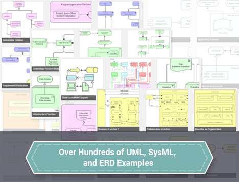
Hundreds of UML and ERD eaxamples ready for importing into Visual Paradigm for instant experiment or to get started with your own UML model. All for FREE.
Reason 6
Upgrade path to the commercial editions for wide spectrum of applications and possibilities
Easy upgrading for a huge set of additional features (say, BPMN and team collaboration support) and for commercial use, starting at $6 / month.
Reason 7
Active user forum to get helps and exchange ideas & Experiences
Support, share and exchange your ideas with other people in the Visual Paradigm’s active user forum.

Reason 8
Cross-Platform, user friendly, fast & responsive application
Visual Paradigm can run on different platforms such as Windows, Linux and Mac. Its intuitive interface and powerful modeling features make modeling fast and easy!

References
- What is UML?
- Why UML Modeling?
- Overview of the 14 UML Diagram Types
- What is Class Diagram?
- What is Component Diagram?
- What is Deployment Diagram?
- What is Object Diagram?
- What is Package Diagram?
- What is Composite Structure Diagram?
- What is Profile Diagram?
- What is Use Case Diagram?
- What is Activity Diagram?
- What is State Machine Diagram?
- What is Sequence Diagram?
- What is Communication Diagram?
- What is Interaction Overview Diagram?
- What is Timing Diagram
This post is also available in Deutsch, Español, فارسی, Français, English, Bahasa Indonesia, 日本語, Polski, Portuguese, Ру́сский, Việt Nam, 简体中文 and 繁體中文.