
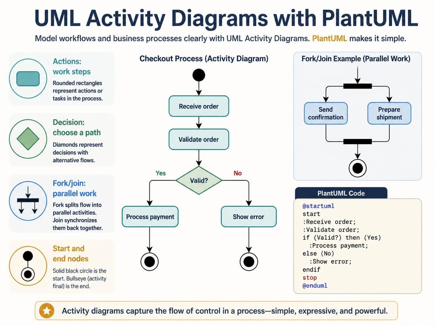
A UML activity diagram models how work flows through a process: the actions performed, decisions made, parallel work, and paths to completion. PlantUML lets you describe that model as text, then render it as a diagram—a useful approach when you want diagrams that are easy to revise, review, and keep alongside project documentation. PlantUML’s current activity syntax uses readable keywords such as start, if, repeat, and fork; its older activity syntax is still supported, but the newer syntax is recommended for new diagrams.
1. What to model
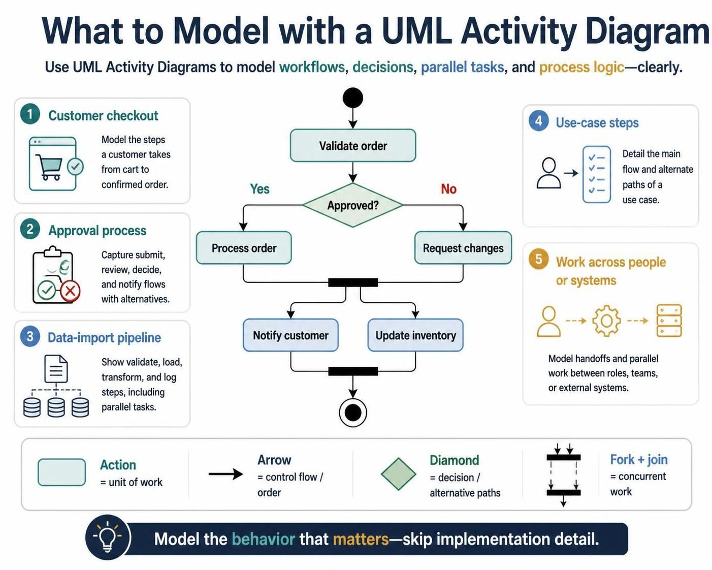
Use an activity diagram to explain a process or algorithm, for example:
-
A customer checkout workflow
-
An approval process
-
A data-import pipeline
-
The steps in a use case
-
Work split across people, teams, or system components
An activity is a unit of work, such as “Validate order.” A control flow connects activities and indicates their order. A decision chooses among alternative paths; parallel flows show work that can proceed concurrently. The diagram should clarify behavior, not attempt to document every implementation detail.
A useful rule of thumb: if the main question is “What happens next, and under what condition?”, an activity diagram is a good fit.
2. PlantUML basics
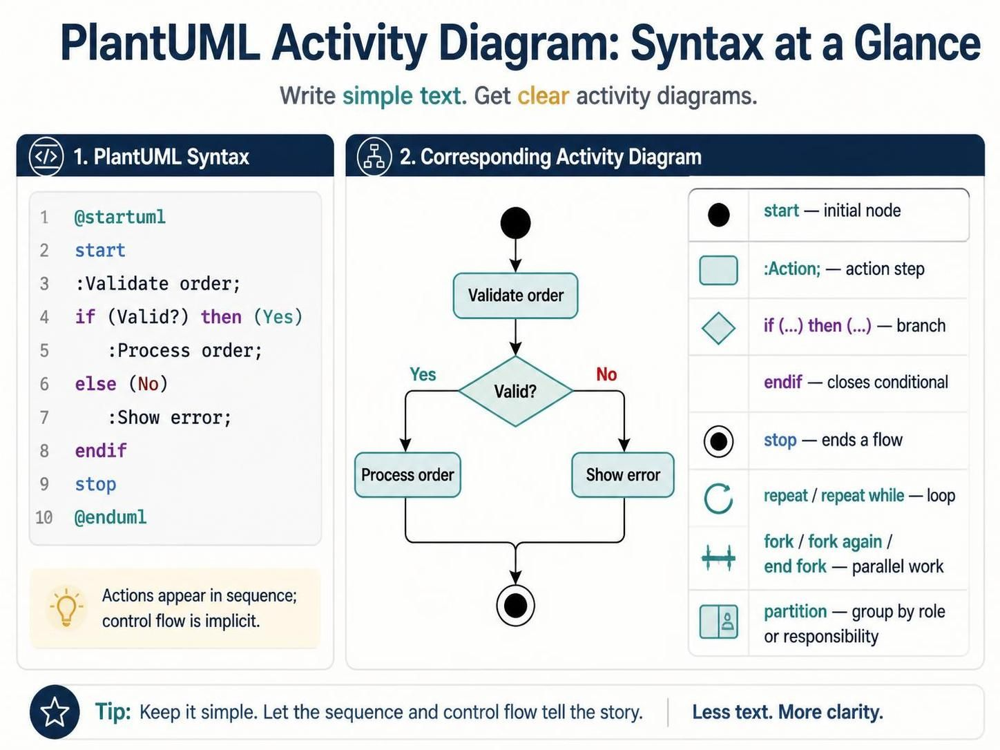
A PlantUML diagram begins with @startuml and ends with @enduml. In the current activity syntax:
-
startmarks the initial node. -
:Action;defines an action. -
if (...) then (...)branches on a condition. -
endifcloses the conditional. -
stopends a flow. -
repeatandrepeat whilemodel repetition. -
fork,fork again, andend forkmodel parallel work.
Actions are written in order and are implicitly connected. You can add labels to branches and use partition to group work by responsibility or role.
Here’s a minimal example:
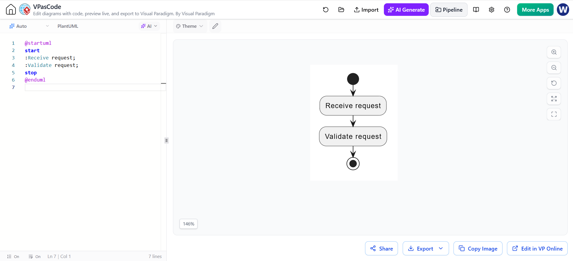
@startuml
start
:Receive request;
:Validate request;
stop
@enduml
3. Decisions and alternative paths
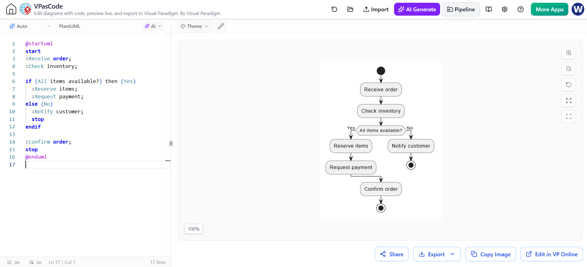
Use if when the process makes a choice. Branch labels should communicate the condition’s outcomes, not merely repeat the condition.
@startuml
start
:Receive order;
:Check inventory;

if (All items available?) then (Yes)
  :Reserve items;
  :Request payment;
else (No)
  :Notify customer;
  stop
endif

:Confirm order;
stop
@enduml
Here, if introduces a decision and endif closes it. The Yes and No labels make the alternatives visible. When the paths continue to a shared action after endif, they rejoin the flow.
Modeling tip: Be explicit about what happens on every meaningful outcome. If an error, timeout, or rejection path matters to stakeholders, show it rather than leaving it implicit.
4. Loops and retries
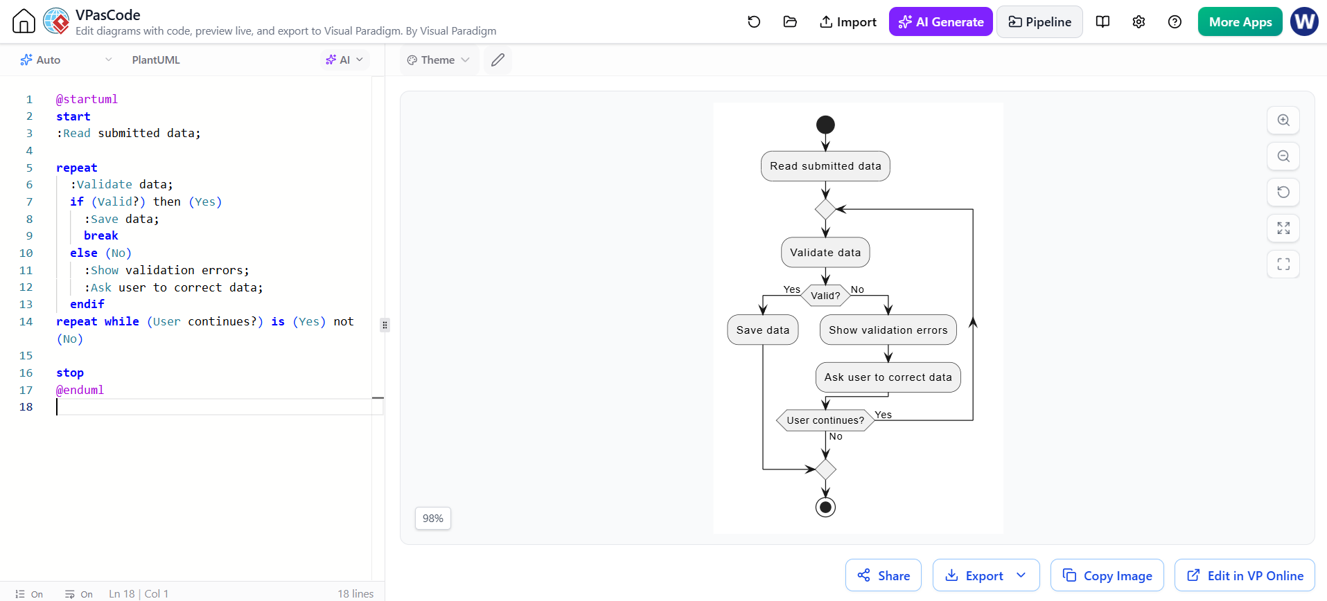
Use a loop when an action or group of actions can repeat. This example keeps asking for input until it passes validation:
@startuml
start
:Read submitted data;

repeat
  :Validate data;
  if (Valid?) then (Yes)
    :Save data;
    break
  else (No)
    :Show validation errors;
    :Ask user to correct data;
  endif
repeat while (User continues?) is (Yes) not (No)

stop
@enduml
Loops can be tricky to read if their exit condition is vague. State what causes another attempt and what ends the repetition—especially when retries are limited or can be cancelled.
5. Parallel work and synchronization
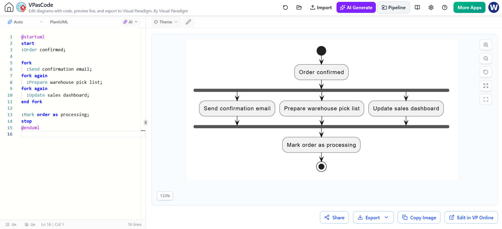
Use fork when independent actions can happen concurrently, and end fork when the paths must synchronize before the process continues.
@startuml
start
:Order confirmed;

fork
  :Send confirmation email;
fork again
  :Prepare warehouse pick list;
fork again
  :Update sales dashboard;
end fork

:Mark order as processing;
stop
@enduml
A fork does not necessarily mean separate people; it can represent concurrent system behavior. Only use it when the actions really can happen in parallel. If one task must finish before another starts, model them sequentially instead.
6. Swimlanes with partitions
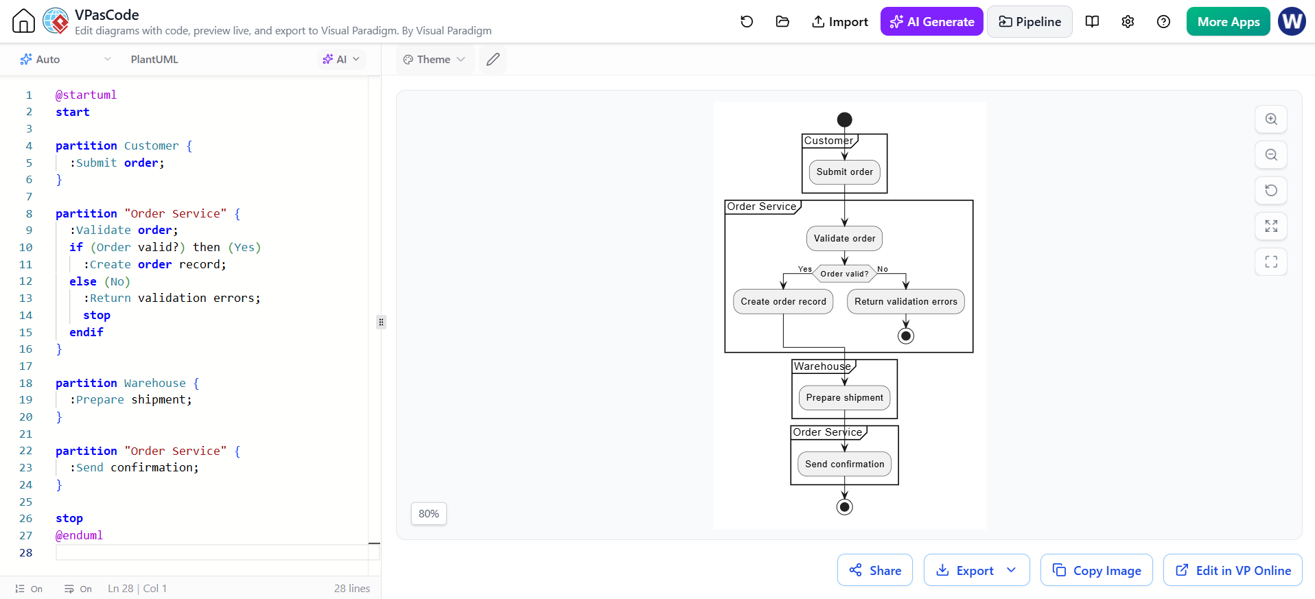
Partitions group actions by the role, team, or system responsible. This can make handoffs clear without changing the process itself. PlantUML supports grouping activities with partition.
@startuml
start

partition Customer {
  :Submit order;
}

partition "Order Service" {
  :Validate order;
  if (Order valid?) then (Yes)
    :Create order record;
  else (No)
    :Return validation errors;
    stop
  endif
}

partition Warehouse {
  :Prepare shipment;
}

partition "Order Service" {
  :Send confirmation;
}

stop
@enduml
Choose lane labels that match the real division of responsibility. Avoid creating a new partition for every small component; too many lanes can make the diagram harder to scan.
7. Data objects and notes
Some workflows benefit from showing important inputs or outputs. PlantUML activity diagrams support object-node stereotypes; notes can also add context without turning every action label into a paragraph.
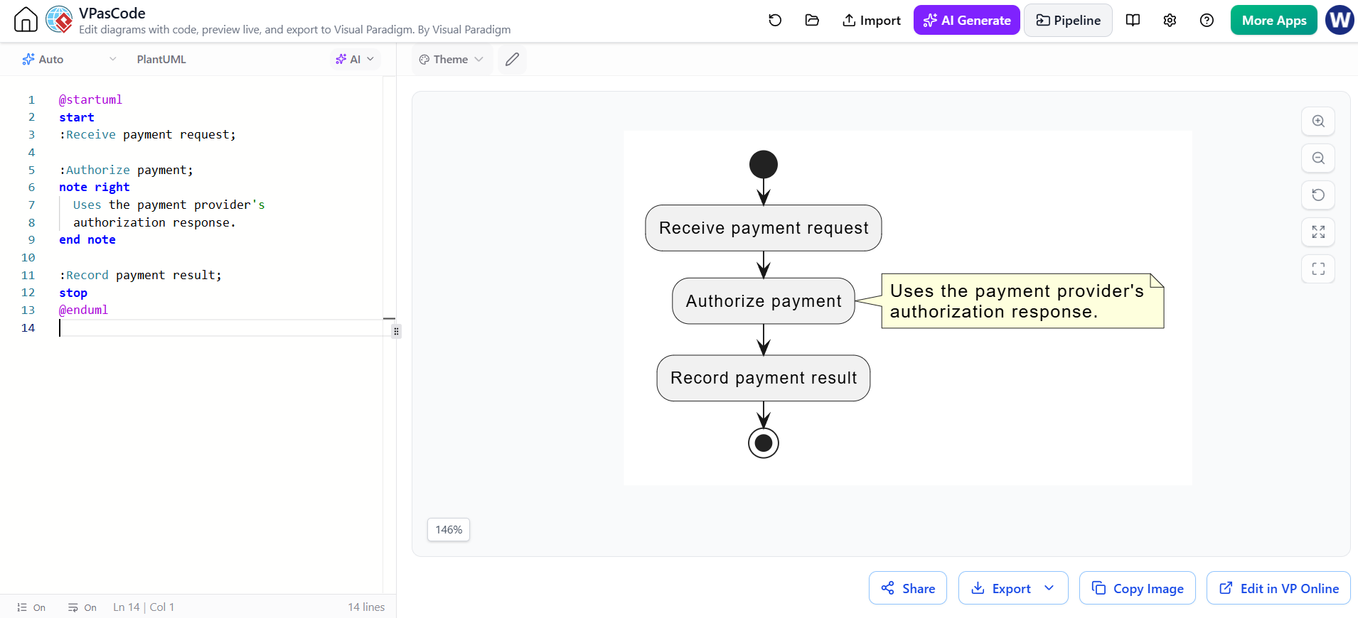
@startuml
start
:Receive payment request;

:Authorize payment;
note right
  Uses the payment provider's
  authorization response.
end note

:Record payment result;
stop
@enduml
Keep the main activity labels short. Put business rules, assumptions, or clarifications in notes when readers need them but they are not themselves steps in the flow.
8. Complete example: online checkout
This larger example combines partitions, a decision, an alternative path, and parallel work.
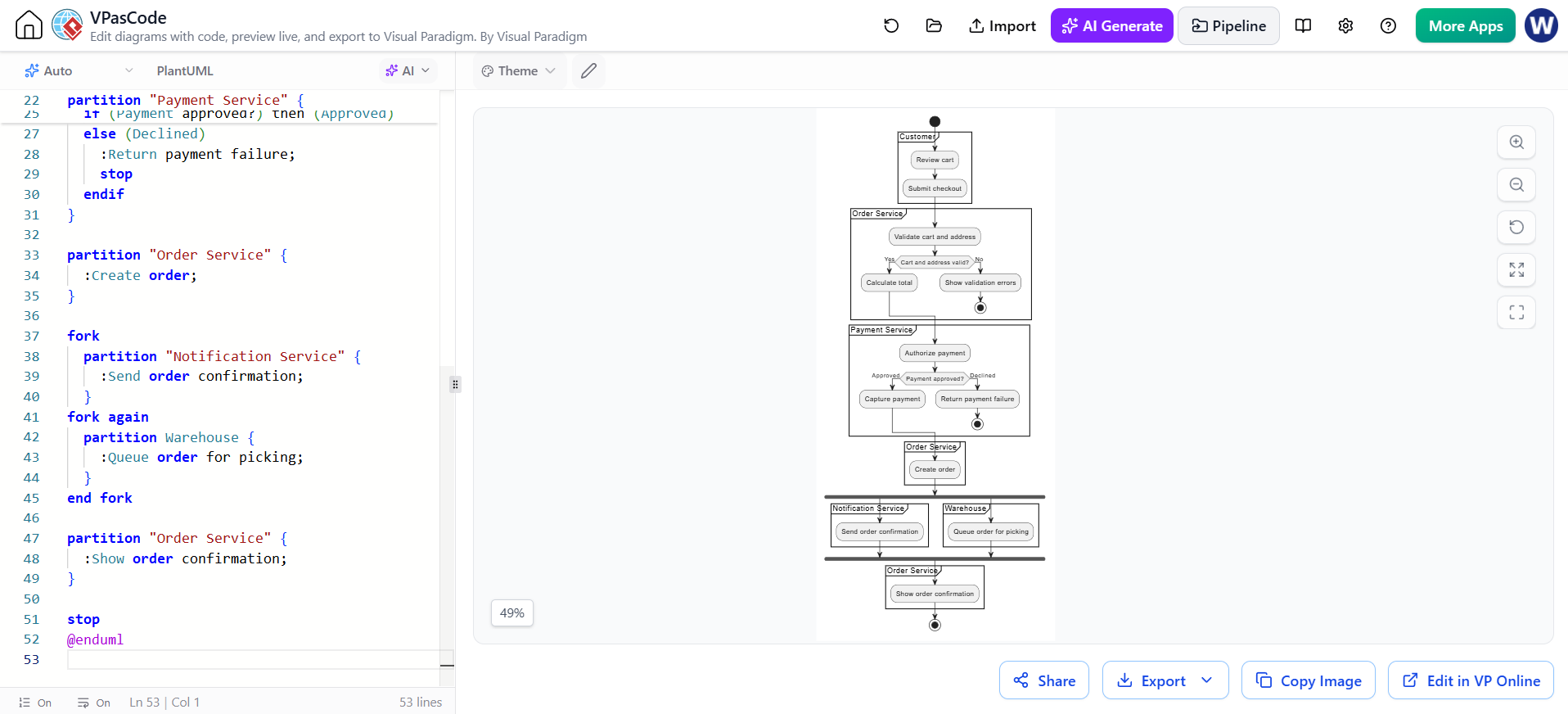
@startuml
title Online Checkout

start

partition Customer {
  :Review cart;
  :Submit checkout;
}

partition "Order Service" {
  :Validate cart and address;

  if (Cart and address valid?) then (Yes)
    :Calculate total;
  else (No)
    :Show validation errors;
    stop
  endif
}

partition "Payment Service" {
  :Authorize payment;

  if (Payment approved?) then (Approved)
    :Capture payment;
  else (Declined)
    :Return payment failure;
    stop
  endif
}

partition "Order Service" {
  :Create order;
}

fork
  partition "Notification Service" {
    :Send order confirmation;
  }
fork again
  partition Warehouse {
    :Queue order for picking;
  }
end fork

partition "Order Service" {
  :Show order confirmation;
}

stop
@enduml
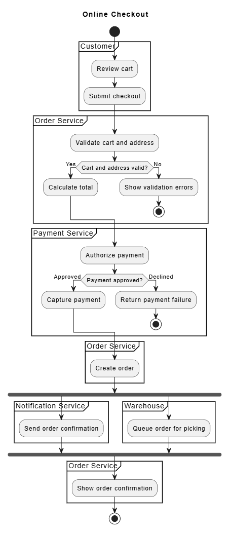
Read it from top to bottom: the customer submits the checkout, the order service validates it, payment is authorized, and the order is created. Afterward, confirmation and warehouse preparation run in parallel. If validation or payment fails, the flow ends through the relevant failure path.
9. Diagram-as-code workflow
A practical workflow is:
Diagram-as-code workflow
A practical workflow is:
-
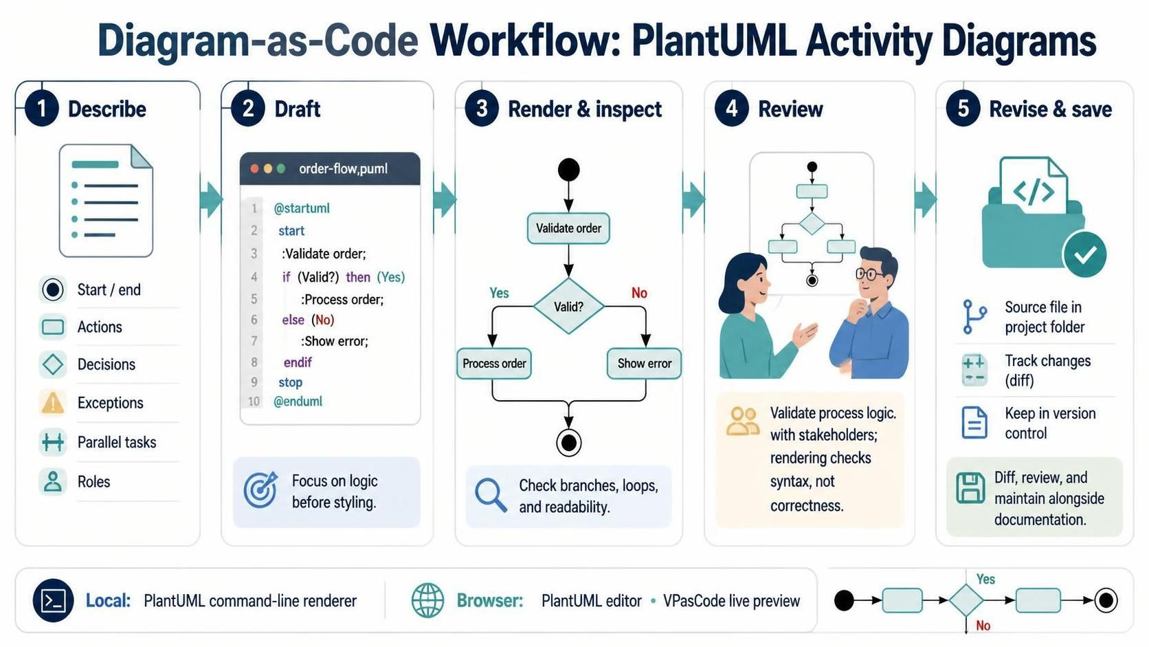
Describe the process in plain language. Identify its start, end, main actions, decisions, exceptions, parallel tasks, and responsible roles.
-
Write a first PlantUML draft. Focus on the logic before styling.
-
Render and inspect it. Check that the result reads naturally and that branches and loops are understandable.
-
Review the logic with stakeholders. Rendering checks syntax—not whether the process is correct.
-
Revise the source and save it with the project. Text-based diagrams are straightforward to diff and review alongside other documentation.
For local rendering, the PlantUML command-line tool can generate diagram files; browser-based editors are convenient for quick drafts and previews. PlantUML also offers a browser editor, while VPasCode provides a browser-based editor with live preview and PlantUML activity-diagram support.
-
Describe the process in plain language. Identify its start, end, main actions, decisions, exceptions, parallel tasks, and responsible roles.
-
Write a first PlantUML draft. Focus on the logic before styling.
-
Render and inspect it. Check that the result reads naturally and that branches and loops are understandable.
-
Review the logic with stakeholders. Rendering checks syntax—not whether the process is correct.
-
Revise the source and save it with the project. Text-based diagrams are straightforward to diff and review alongside other documentation.
For local rendering, the PlantUML command-line tool can generate diagram files; browser-based editors are convenient for quick drafts and previews. PlantUML also offers a browser editor, while VPasCode provides a browser-based editor with live preview and PlantUML activity-diagram support.
10. Using Visual Paradigm VPasCode and AI assistance
VPasCode is Visual Paradigm’s browser-based text-to-diagram editor. Its PlantUML support includes activity diagrams, and its editor provides live rendering. Visual Paradigm also describes built-in natural-language diagram generation and AI assistance for modifying or correcting diagram code.
A useful AI-assisted workflow:
-
Prompt for the behavior, not just the diagram type. For example:
“Create a PlantUML activity diagram for online checkout. Include cart validation, address validation, payment authorization, failure paths, order creation, and parallel confirmation email and warehouse preparation. Use partitions for Customer, Order Service, Payment Service, Notification Service, and Warehouse. Use the current PlantUML activity syntax.” -
Inspect the generated source. Check that it uses
@startuml/@enduml, that each branch represents a real condition, and that failed or alternate paths are handled. -
Render it in VPasCode. Use the preview to spot syntax errors, confusing labels, or overly complex layouts.
-
Refine the PlantUML yourself or with targeted AI edits. Ask for a specific change, such as “Add a payment timeout path” or “Make warehouse preparation sequential after order creation.”
-
Validate the process with someone who knows it. AI can draft a plausible diagram, but it cannot establish that your organization’s actual process is correct.
VPasCode’s exact controls and feature availability can vary by product edition; confirm the current options in the editor you’re using.
11. Visual Paradigm modeling workflow
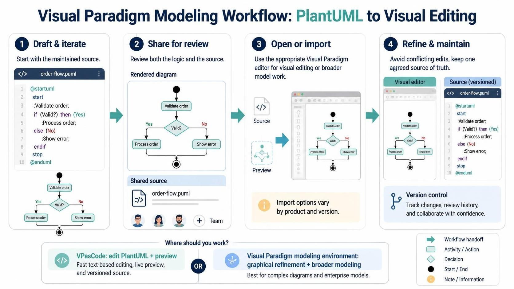
Use VPasCode when you want to work directly with diagram source and preview. Use Visual Paradigm’s modeling environment when the task calls for graphical editing or broader model work. Visual Paradigm’s guidance describes a workflow of generating or importing a diagram, then refining it in the visual editor; exact import paths can depend on the product and version.
A sensible handoff is:
-
Draft and iterate in PlantUML.
-
Share the rendered diagram and source for review.
-
Open or import it into the relevant Visual Paradigm editor if you need visual editing or other modeling capabilities.
-
Keep the PlantUML source as the maintained version if it is the team’s chosen source of truth; avoid silently making conflicting edits in two places.
12. Common mistakes and quality checklist
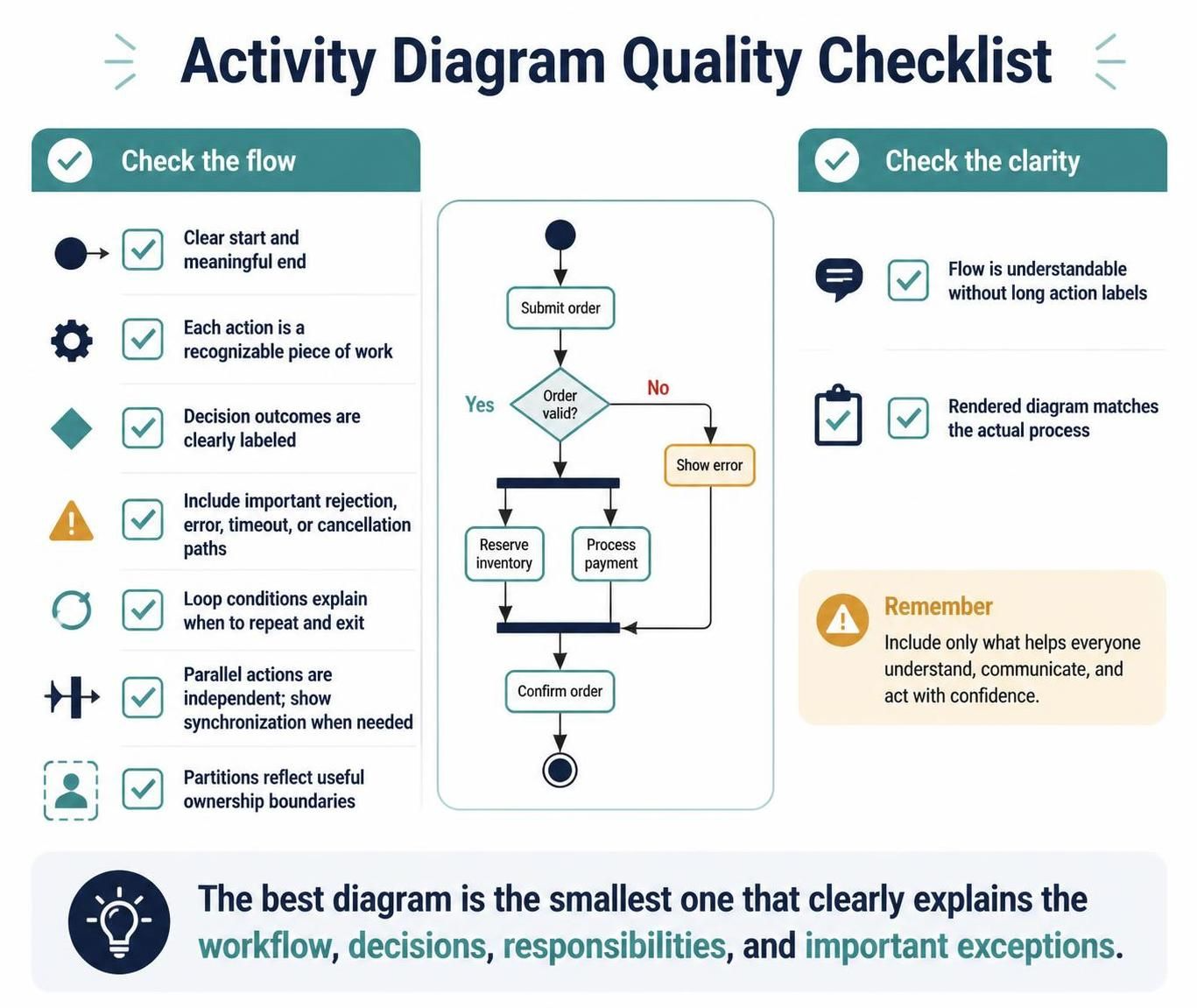
Before sharing a diagram, check:
-
Does it have a clear start and a meaningful end?
-
Does each action describe a recognizable piece of work?
-
Are decision outcomes labeled clearly?
-
Are rejection, error, timeout, or cancellation paths included where they matter?
-
Do loop conditions make repeat and exit behavior clear?
-
Are parallel actions genuinely independent, and is synchronization shown where needed?
-
Do partitions represent useful ownership boundaries?
-
Can a reader understand the flow without reading long action labels?
-
Does the rendered diagram match the actual process?
A good activity diagram is not the longest or most detailed one. It is the smallest diagram that makes the workflow, decisions, responsibilities, and important exceptions clear.
Quick syntax reference
| Purpose | PlantUML pattern |
|---|---|
| Start | start |
| Action | :Do something; |
| Decision | if (Condition?) then (Yes) ... else (No) ... endif |
| Loop | repeat ... repeat while (Condition?) |
| Parallel work | fork ... fork again ... end fork |
| Responsibility group | partition Role { ... } |
| End | stop |
The examples use PlantUML’s current activity-diagram syntax. For uncommon constructs or version-specific rendering behavior, check the PlantUML activity diagram reference.