


Suggested Article Title: “From Theory to Practice: A Real-World Guide to UML Communication Diagrams with Visual Paradigm”
Introduction: Why Communication Diagrams Matter in Modern System Design
As software systems grow increasingly complex, the ability to visualize how objects interact becomes not just helpful—but essential. While sequence diagrams often steal the spotlight in UML documentation, communication diagrams offer a uniquely powerful perspective that many practitioners overlook.

Having worked with multiple modeling tools across enterprise projects, I’ve found that communication diagrams shine when you need to understand who talks to whom rather than just when. This guide shares my hands-on experience creating communication diagrams using Visual Paradigm, blending official documentation insights with practical tips I’ve gathered along the way. Whether you’re a seasoned architect or a developer new to UML, you’ll find actionable value here.
What Is a Communication Diagram?
A communication diagram (formerly called a collaboration diagram in UML 1.x) is an interaction diagram that models the interactions between objects or parts in terms of sequenced messages. Its primary focus is on object relationships rather than strict chronological ordering.
Key characteristics:
-
Uses a free-form arrangement of objects and links, similar to Object diagrams
-
Messages are labeled with chronological numbers (e.g., 1.0, 1.1, 2.0) and placed near the link they traverse
-
Reading starts at message 1.0 and follows the numbered sequence from object to object
-
Emphasizes structural organization: which elements interact and how they’re connected
Communication Diagrams vs. Sequence Diagrams: When to Use Which
Both diagrams convey similar interaction information, but their presentation creates distinct advantages:
| Feature | Communication Diagram | Sequence Diagram |
|---|---|---|
| Primary Focus | Object relationships & links | Time-ordered message flow |
| Layout | Free-form, spatial arrangement | Vertical timeline, top-to-bottom |
| Best For | Understanding structural dependencies | Tracing exact execution order |
| Readability | Easier to see “who interacts with whom” | Easier to follow “what happens when” |
💡 Pro Tip from Experience: I typically start with a communication diagram during early design workshops to map object collaborations, then refine critical flows into sequence diagrams for implementation specs. This two-step approach saves time and reduces miscommunication.
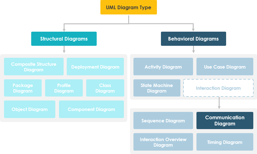
The UML Interaction Diagram Family
UML defines four types of interaction diagrams, each serving a unique purpose:
Understanding where communication diagrams fit within this ecosystem helps you select the right tool for your modeling goal.
How to Draw a Communication Diagram in UML: A Visual Paradigm Walkthrough
Note: This section reflects my actual workflow using Visual Paradigm v17. Details may vary slightly by version.
Creating a New Communication Diagram
-
Select Diagram > New from the application toolbar.
-
In the New Diagram window, select Communication Diagram.
-
Click Next.
-
Enter the diagram name and description. The Location field enables you to select a model to store the diagram.
-
Click OK.
Creating an Actor
To create an actor, click Actor on the diagram toolbar and then click on the diagram.
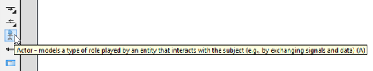
🎯 User Insight: I always name actors using role-based terminology (e.g., “Customer,” “PaymentService”) rather than implementation classes. This keeps diagrams accessible to non-technical stakeholders during reviews.
Creating Lifelines: Two Methods Compared
Method 1: Toolbar Approach
Click LifeLine on the diagram toolbar and then click on the diagram.
Method 2: Resource Catalog (My Preferred Method)
-
Move your mouse pointer over the source lifeline.
-
Press on the Resource Catalog button and drag it out.
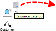
-
Release the mouse button at the place where you want the lifeline to be created.
-
Select Message -> LifeLine from Resource Catalog.
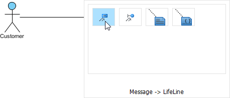
-
A new lifeline will be created and connected to the actor/lifeline with a message. Enter its name and press Enter to confirm editing.
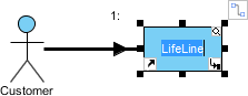
⚡ Efficiency Tip: The Resource Catalog method automatically creates the connecting message link—saving 2-3 clicks per element. Over a complex diagram, this adds up significantly.
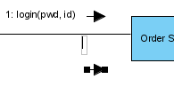
Creating Messages on Links
To create a message on an existing link, click its Create Message resource.
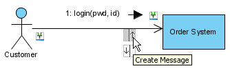
A message will be created on the link.
🔍 Clarity Practice: I use concise, verb-first message names like
validateOrder()orsendConfirmation()to make diagrams self-documenting. Avoid generic names likemessage1.
Editing Sequence Numbers for Nested Interactions
To edit sequence numbers—for example, to show messages within a nested interaction level:
-
Right-click the diagram and select Reorder Messages… from the pop-up menu.
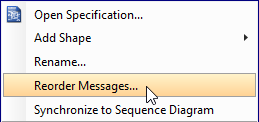
-
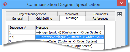
When the Communication Diagram Specification window appears, the Message tab is opened by default. Double-click on the Sequence # cell of a message to edit it.
-
Click OK to apply the changes.
🧩 Modeling Strategy: Use decimal numbering (1.0, 1.1, 1.2) for nested calls. This visually communicates hierarchy without cluttering the diagram with additional notation.
Practical Tips from the Trenches: Maximizing Communication Diagram Value
After using communication diagrams across fintech, healthcare, and e-commerce projects, here are my top recommendations:
✅ Start Simple: Begin with core objects and primary messages. Add complexity iteratively.
✅ Color-Code by Responsibility: Use fill colors to group objects by subsystem or team ownership.
✅ Link to Code: In Visual Paradigm, connect lifelines to actual classes for traceability.
✅ Review with Stakeholders: The spatial layout makes communication diagrams ideal for non-technical reviews.
✅ Version Control Diagrams: Treat diagrams as living documentation—store them alongside source code.
❌ Avoid Over-Engineering: Don’t model every getter/setter. Focus on meaningful interactions.
❌ Don’t Mix Abstraction Levels: Keep business logic and technical implementation in separate diagrams.
❌ Skip the Chronology Trap: If timing is critical, supplement with a sequence diagram—don’t force one diagram to do both jobs perfectly.
Conclusion: Communication Diagrams as Collaborative Design Tools
Communication diagrams aren’t just another UML artifact—they’re a bridge between architectural vision and implementation reality. By emphasizing object relationships over strict timing, they enable teams to align on system structure before diving into procedural details.
My experience confirms that when used intentionally—paired with sequence diagrams for temporal clarity and class diagrams for static structure—communication diagrams significantly reduce design ambiguity and accelerate development. Visual Paradigm’s intuitive tooling lowers the barrier to entry, but the real value comes from disciplined modeling practices and collaborative review.
Whether you’re documenting a microservices architecture, refining a domain model, or onboarding new team members, investing time in clear communication diagrams pays dividends in system understandability and maintainability. Start small, iterate often, and let the diagram evolve with your system.
References
- What is Sequence Diagram?: Comprehensive guide explaining sequence diagrams, their purpose, elements, and best practices in UML modeling.
- What is Communication Diagram?: Official documentation detailing communication diagrams, their structure, use cases, and relationship to other UML interaction diagrams.
- What is Interaction Overview Diagram?: Overview of interaction overview diagrams that combine multiple interaction fragments into a high-level workflow.
- What is Timing Diagram?: Explanation of timing diagrams focused on state changes and constraints over time for real-time systems.
- What is UML?: Foundational introduction to the Unified Modeling Language, its history, purpose, and core concepts.
- Why UML Modeling?: Business and technical rationale for adopting UML, including benefits for communication, design, and documentation.
- Overview of the 14 UML Diagram Types: Complete catalog of all UML diagram types with use cases and selection guidance.
- What is Class Diagram?: Guide to class diagrams for modeling static structure, relationships, and constraints in object-oriented systems.
- What is Object Diagram?: Explanation of object diagrams as instances of class diagrams, useful for illustrating specific scenarios.
- How to draw a Communication Diagram in UML: Step-by-step tutorial with screenshots for creating communication diagrams in Visual Paradigm.
This post is also available in Deutsch, Español, فارسی, Français, English, Bahasa Indonesia, 日本語, Polski, Portuguese, Ру́сский, Việt Nam, 简体中文 and 繁體中文.