


A practitioner’s hands-on review and comprehensive guide to understanding, creating, and leveraging use case diagrams for effective system requirements modeling
🎯 New Introduction
When I first encountered UML use case diagrams in a software engineering course, I’ll be honest—I was overwhelmed. Stick figures, ovals, dashed arrows with stereotypes like <<include>> and <<extend>>… it felt like learning a secret language. But after working on several real-world projects and diving deep into tools like Visual Paradigm, I’ve come to appreciate use case diagrams as one of the most powerful yet underrated artifacts in requirements engineering.

This guide is written from the perspective of someone who’s been in your shoes: a product professional, developer, or student trying to bridge the gap between stakeholder expectations and technical implementation. Whether you’re documenting a new feature, aligning a cross-functional team, or preparing for a certification exam, this comprehensive walkthrough will help you not just draw use case diagrams—but think in use cases.
We’ll cover:
-
✅ What use case diagrams truly are (and what they’re not)
-
✅ A visual notation reference with OMG UML specifications
-
✅ Step-by-step creation workflows in Visual Paradigm
-
✅ Pro tips for keeping diagrams simple and effective
-
✅ How to capture meeting notes and evolve them into actionable scenarios
Let’s dive in.
📘 What Is a Use Case Diagram? (The Big Picture)
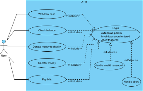
A use case diagram at its simplest is a representation of a user’s interaction with the system that shows the relationship between the user and the different use cases in which the user is involved. A UML use case diagram is the primary form of system/software requirements for a new software program under development.
💡 Key Insight from Experience: Use cases specify the expected behaviour (what), and not the exact method of making it happen (how). This separation of concerns is what makes them so valuable for stakeholder communication.
What Use Case Diagrams Do Well:
-
🎯 Provide a high-level, end-user perspective of system functionality
-
🗣️ Facilitate conversations between technical and non-technical stakeholders
-
🧭 Serve as a “blueprint” for what the system must actually do
-
🔗 Link to detailed specifications, sequence diagrams, or user stories
What They Don’t Show (And That’s Okay):
-
❌ The order in which steps are performed to achieve goals
-
❌ Detailed UI flows or database schemas
-
❌ Implementation logic or algorithmic complexity
⚠️ Practitioner Warning: If your use case diagram contains more than 20 use cases, you’re probably misusing it. Keep it simple. Use packages to group related functionality. Let other diagrams handle the details.
🧩 Use Case Diagram Notations: A Visual Reference Guide
Below is the complete notation reference I keep bookmarked. Each element includes the official OMG UML specification excerpt for those who need formal precision.
| Icon | Name | Purpose & My Practical Notes |
|---|---|---|
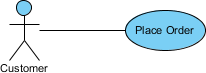
| Use Case | Represents a user goal achievable via the system. Pro tip: Name use cases as verb-noun phrases like “Place Order” or “Generate Report” for clarity. | |
| Association | Connects actors to use cases they participate in. Shows interaction, not data flow. | |
| Actor | External entity interacting with the system. Remember: Actors represent roles (e.g., “Customer”), not specific people (e.g., “John Doe”). | |
| System | The system boundary. Use cases go inside; actors stay outside. Clarifies scope. | |
| Include | Mandatory behavior reuse. Base use case always executes the included one. | |
| Extend | Optional/conditional behavior. Extension executes only under specific conditions at defined extension points. | |
| Dependency | One element relies on another for specification or implementation. Use sparingly in use case diagrams. | |
| Generalization | Inheritance relationship. Specific classifier inherits features of the general one. | |
| Realization | Links a specification to its implementation. More common in class/component diagrams. | |
| Collaboration | Describes how roles collaborate to achieve functionality. Abstracts away instance details. |
🔍 Deep Dive: Core Notations Explained
Use Case

A use case represents a user goal that can be achieved by accessing the system or software application. In Visual Paradigm, you can make use of the sub-diagram feature to describe the interaction between user and system within a use case by creating a sub-sequence diagram under a use case. You can also describe the use case scenario using the Flow of Events editor.
OMG UML Specification:
“A use case is the specification of a set of actions performed by a system, which yields an observable result that is typically of value for one or more actors or other stakeholders of the system.”
— UML Superstructure Specification v2.4.1, p.606
Actor

Actors are the entities that interact with a system. Although in most cases, actors are used to represent the users of system, actors can actually be anything that needs to exchange information with the system. So, an actor may be people, computer hardware, other systems, etc.
OMG UML Specification:
“An actor specifies a role played by a user or any other system that interacts with the subject… An Actor models a type of role played by an entity that interacts with the subject but which is external to the subject.”
— UML Superstructure Specification v2.4.1
Include vs. Extend: The Critical Distinction
| Relationship | When to Use | Direction | My Rule of Thumb |
|---|---|---|---|
<<include>> |
When behavior is always required | Base → Included | “This step is mandatory for the main flow” |
<<extend>> |
When behavior is conditional or optional | Extending → Base | “This only happens if X condition is met” |
💡 Real-World Example:
Place OrderincludesValidate Payment(always required)
Place Ordercan be extended byApply Promo Code(only if user has a code)
🛠️ How to Draw a Use Case Diagram: My Visual Paradigm Workflow
After testing several UML tools, I settled on Visual Paradigm for its balance of rigor and usability. Here’s my battle-tested workflow:
Step 1: Create the Diagram
-
Select Diagram > New from the application toolbar.
-
In the New Diagram window, select Use Case Diagram.
-
Click Next.
-
Enter the diagram name and description. The Location field enables you to select a model to store the diagram.
-
Click OK.
Step 2: Define System Boundary
To create a system in use case diagram, select System on the diagram toolbar and then click it on the diagram pane. Finally, name the newly created system when it is created.
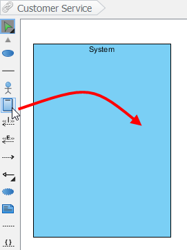
✅ Best Practice: Name your system clearly (e.g., “E-Commerce Platform” not “System1”). This becomes your scope anchor.
Step 3: Add Actors
To draw an actor in use case diagram, select Actor on the diagram toolbar and then click it on the diagram pane. Finally, name the newly created actor when it is created.
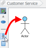
🎯 Pro Tip: Start with primary actors (those who initiate use cases), then add secondary actors (systems or roles that support).
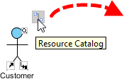
Step 4: Create Use Cases (The Smart Way)
Besides creating a use case through diagram toolbar, you can also create it through Resource Catalog:
-
Move the mouse over a source shape (e.g. an actor).
-
Press on the Resource Catalog button and drag it out.
-
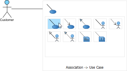
Release the mouse button until it reaches your preferred place.
-
Select Association -> Use Case from Resource Catalog.
-
The source shape and the newly created use case are connected. Finally, name the newly created use case.
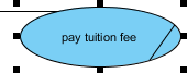
Step 5: Handle Long Use Case Names
If a use case is too wide, you may resize it by dragging the filled selectors for a better outlook. As a result, the name of use case will be line-wrapped automatically.
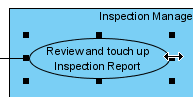
⌨️ Keyboard Shortcut: Press Alt + Enter to force a new line manually.
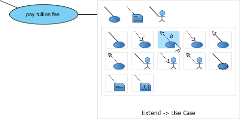
Step 6: Add <> and <> Relationships
For Extend:
-
Move the mouse over a use case, press and drag out its Resource Catalog button.
-
Release the mouse button at the preferred place and select Extend -> Use Case.
-
Name the new use case and define extension points.
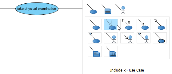
For Include:
-
Same drag-from-Resource-Catalog approach.
-
Select Include -> Use Case.
-
Name the included use case.
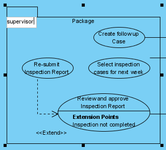
Step 7: Organize with Packages (When Needed)
You can organize use cases with package when there are many of them on the diagram.
-
Select Package on the diagram toolbar.
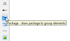
-
Drag the mouse to create a package surrounding those use cases.
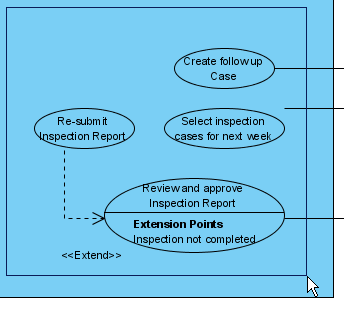
-
Finally, name the package.
Bonus: Business Use Cases
The UML diagram tool also supports the representation of business actor and use case. To show an ordinary use case as business use case:
-
Right click on a use case and select Model Element Properties > Business Model.
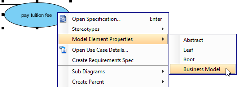
-
After selected, an extra slash will be shown on the left edge of the use case.
📝 Capturing Requirements: Use Case Notes & Meeting Workflow
One feature that transformed my requirements process: Use Case Notes. While meeting with users is an important part of requirements capturing, multiple meetings are essential for clarifying what user really wants. Use Case Notes is designed for you to note down the discussion during requirements capturing meetings.
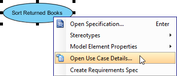
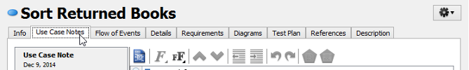
Accessing Use Case Notes
-
Right-click on a use case → Open Use Case Details…
-
Open the Use Case Notes tab.
Entering Notes with Structure
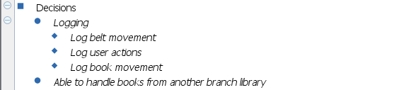
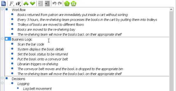
Once opened, you’ll see a pre-defined template with four points: Workflow, Business Logic, Decisions, and Follow-up.
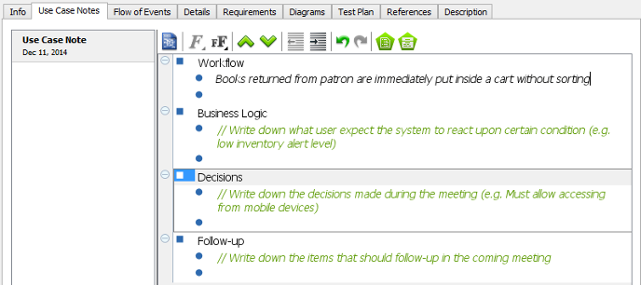
✏️ My Template Enhancement: I add two custom sections:
Stakeholder Concerns: Capture objections or risks raised
Acceptance Criteria: Draft testable conditions early
Working with Nested Notes
Different kinds of use case-related ideas can be recorded by creating multiple nested notes. Press Tab to indent, Shift+Tab to reduce indentation.
🚀 From Notes to Scenarios: One-Click Evolution
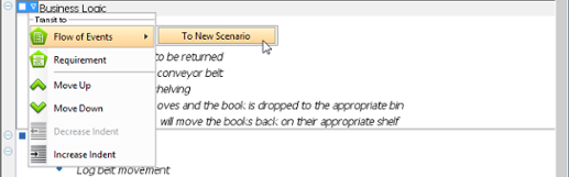
When stakeholders describe preferred system behaviors, you can turn notes into formal scenarios:
-
Hover over a parent note item containing behavior descriptions.
-
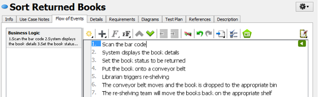
Click the down arrow next to the bullet → Flow of Events > To New Scenario.
-
Voilà: A new scenario is produced with note text as scenario name and sub-notes as steps.
🔁 Iterative Workflow I Use:
Meeting → Notes → Draft Scenario → Stakeholder Review → Refined Use Case → Linked Sequence Diagram
🎯 New Conclusion: When to Use (and When to Skip) Use Case Diagrams
After years of applying use case diagrams across startups and enterprise projects, here’s my distilled advice:
✅ Use Use Case Diagrams When:
-
You need to align business stakeholders and developers on what the system should do
-
You’re documenting scope for a new product or major feature release
-
You want to identify missing actors or edge-case interactions early
-
You’re preparing user stories for agile sprints (use cases = epic-level granularity)
❌ Consider Alternatives When:
-
You’re modeling highly technical, internal system interactions (try component or deployment diagrams)
-
You need to specify real-time behavior or concurrency (state machines or sequence diagrams are better)
-
Your audience is exclusively developers who prefer code-first specifications
Final Thought:
Use case diagrams aren’t about perfection—they’re about communication. A slightly imperfect diagram that gets everyone on the same page is infinitely more valuable than a “correct” diagram that sits unused in a repository.
🌟 My Golden Rule: If you can’t explain your use case diagram to a non-technical stakeholder in 5 minutes, simplify it further.
Start simple. Iterate with feedback. Let the diagram evolve alongside your understanding of the problem space. That’s how use case modeling becomes a strategic advantage—not just a documentation chore.
📚 Reference
- What is a Use Case?: Foundational Wikipedia article defining use cases as specifications of system actions that yield observable, valuable results for stakeholders.
- Unified Modeling Language (UML): Overview of UML as a standardized modeling language for visualizing, specifying, constructing, and documenting software systems.
- What is UML?: Beginner-friendly introduction to UML concepts, diagram types, and modeling principles from Visual Paradigm’s learning guide.
- Why UML Modeling?: Practical justification for adopting UML, covering benefits like improved communication, reduced ambiguity, and better design documentation.
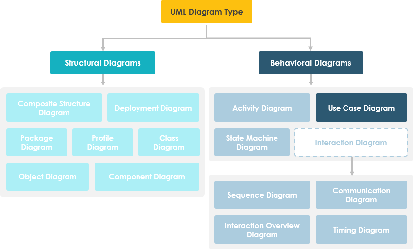
- What is Use Case Diagram?: Core guide explaining the purpose, scope, and positioning of use case diagrams within behavioral UML diagrams.
- Use Case Diagram Notations Guide: Comprehensive visual reference for all UML use case diagram symbols, relationships, and OMG specification excerpts.
- How to Draw a Use Case Diagram in UML: Step-by-step tutorial for creating use case diagrams in Visual Paradigm, including system boundaries, actors, relationships, and organization techniques.
- Entering Meeting Notes for Use Case: Advanced workflow guide for capturing stakeholder discussions in Use Case Notes and evolving them into formal scenarios and requirements.
This post is also available in Deutsch, Español, فارسی, Français, English, Bahasa Indonesia, 日本語, Polski, Portuguese, Ру́сский, Việt Nam, 简体中文 and 繁體中文.