


In the landscape of software engineering and business analysis, two modeling standards dominate the conversation: Business Process Model and Notation (BPMN) and Unified Modeling Language (UML). Both serve critical functions in system design, yet they target different audiences and solve distinct problems. Understanding the nuances between these languages is essential for analysts and developers who aim to bridge the gap between business requirements and technical implementation.
Choosing the wrong notation can lead to communication breakdowns, misaligned expectations, and technical debt. This guide provides a detailed examination of BPMN and UML, exploring their strengths, limitations, and ideal use cases without relying on hype or specific software tools.
📊 Understanding BPMN: The Language of Business Processes 🏢
BPMN is designed primarily for business stakeholders, including process owners, managers, and analysts. Its core purpose is to define business processes in a way that is understandable to non-technical participants while remaining precise enough for execution engines. The notation focuses on the flow of activities, decisions, and events within an organization.
Key Characteristics of BPMN
- Process-Centric: The primary focus is on the end-to-end flow of work.
- Event-Driven: It emphasizes triggers and outcomes that start or end a process.
- Swimlanes: Visualizes responsibility through pools and lanes, clarifying who performs each step.
- Standardized Semantics: Defined by the Object Management Group (OMG), ensuring consistency across different modeling environments.
BPMN diagrams are often used to document current state workflows (As-Is) and design future workflows (To-Be). They utilize specific shapes to denote different elements:
- Events: Circles indicating the start, intermediate, or end of a process.
- Activities: Rounded rectangles representing tasks or work.
- Gateways: Diamonds used for decision points or merging flows.
- Sequence Flows: Solid arrows showing the order of steps.
One of the strongest aspects of BPMN is its ability to map directly to execution logic. Complex gateways, such as exclusive gateways (XOR) or parallel gateways (AND), translate easily into programmatic logic. This makes it a valuable asset for automation initiatives.
🧩 Understanding UML: The Language of Systems 💻
UML is a broader standard intended for specifying, constructing, and documenting the artifacts of software systems. While BPMN looks at the business flow, UML looks at the system structure and behavior. It is deeply rooted in object-oriented design and is widely adopted by developers and architects.
Key Characteristics of UML
- Structure-Oriented: Class diagrams define data models and relationships between objects.
- Behavior-Oriented: Sequence, state, and activity diagrams describe how the system reacts to inputs.
- Technical Depth: Focuses on interfaces, methods, and attributes rather than business roles.
- Flexibility: A large suite of diagram types allows for granular system analysis.
UML diagrams are categorized into structural and behavioral diagrams:
- Structural Diagrams: Class, Object, Component, and Deployment diagrams.
- Behavioral Diagrams: Use Case, Activity, Sequence, State Machine, and Communication diagrams.
For developers, UML provides a blueprint for code generation and architectural planning. It helps visualize complex interactions between modules and ensures that the system design aligns with software engineering principles.
⚖️ Core Differences at a Glance
To quickly grasp the distinctions, consider the following comparison table. This highlights the primary focus, audience, and typical output for each notation.
| Feature | BPMN | UML |
|---|---|---|
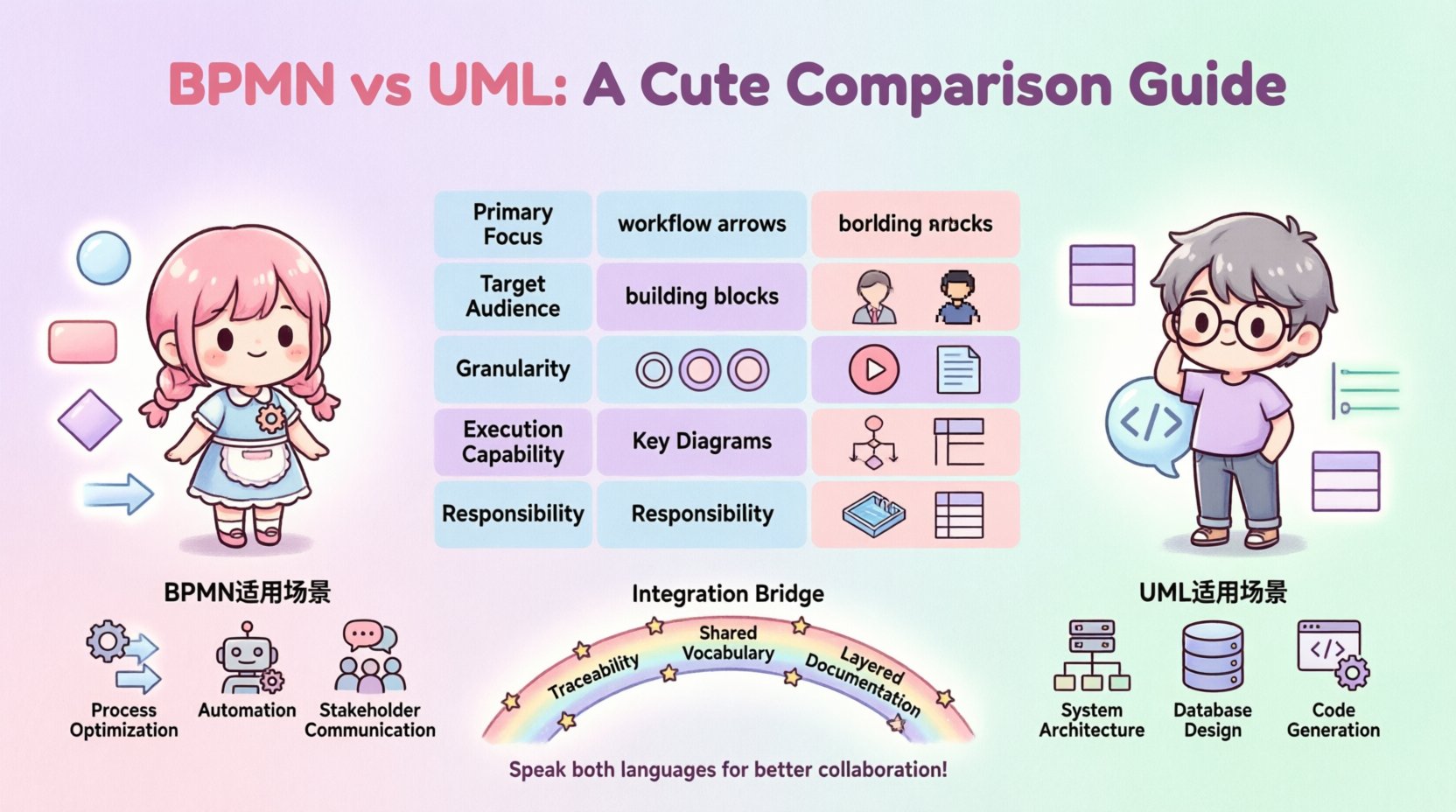
| Primary Focus | Business Processes & Workflows | System Structure & Behavior |
| Target Audience | Business Analysts, Stakeholders | Developers, Architects |
| Granularity | High-level to Detailed Process | System to Code Level |
| Execution Capability | Directly executable (BPMN 2.0) | Design guidance (Code generation varies) |
| Key Diagrams | Process Diagram, Collaboration Diagram | Class, Sequence, State Machine |
| Responsibility | Swimlanes (Who does what) | Classes/Objects (What exists) |
🔍 Deep Dive: Semantic Overlap and Distinctions
While the table above provides a summary, the real value lies in understanding where these languages intersect and diverge in practice. Both standards utilize flow-based logic, but the semantics of that flow differ significantly.
1. Flow Control Mechanisms
BPMN uses gateways to control the path of a process. An Exclusive Gateway (XOR) forces a single path based on a condition. A Parallel Gateway (AND) splits the flow into multiple simultaneous paths. These concepts are similar to UML Activity Diagrams, which also use decision nodes and forks.
However, UML introduces State Machine Diagrams, which focus on the lifecycle of a single object. If you are modeling a ticket in a support system that moves from “Open” to “In Progress” to “Closed,” a UML State Machine is often more appropriate than a BPMN process diagram. BPMN handles the workflow across multiple actors, while UML handles the state changes of a specific entity.
2. Interaction Modeling
When modeling how components communicate, UML Sequence Diagrams are the industry standard. They show the time-ordered sequence of messages exchanged between objects. BPMN Collaboration Diagrams can also show interactions between pools, but they are generally less detailed regarding message syntax and object states.
If the question is “How does the API receive the request and return the response?” UML Sequence Diagrams are the answer. If the question is “How does the order approval process flow from sales to finance to shipping?” BPMN is the answer.
3. Data and Responsibility
BPMN swimlanes define responsibility. A lane represents a specific actor, department, or system. This is crucial for understanding the human or system involvement in a process. UML Class Diagrams define data attributes and relationships. They do not inherently capture the “who” of a process, only the “what” of the data structure.
Developers often struggle when BPMN diagrams are handed off without clear data definitions. Conversely, business stakeholders often find UML Class Diagrams too abstract, as they lack the context of the business workflow.
🛠️ Choosing the Right Tool for the Job
Selecting the correct notation depends on the phase of the project and the specific goals of the modeling effort. Here are practical scenarios for each.
When to Use BPMN
- Process Optimization: When analyzing bottlenecks in a business workflow.
- Automation Projects: When preparing processes for execution in a workflow engine.
- Stakeholder Communication: When explaining the process to non-technical management.
- Compliance & Auditing: When documenting steps required for regulatory adherence.
- Service Orchestration: When defining how multiple services interact in a sequence.
When to Use UML
- System Architecture: When designing the overall structure of a software application.
- Database Design: When mapping entities and relationships for a data model.
- Interface Definition: When specifying method signatures and API contracts.
- Object Lifecycle: When tracking the state changes of a specific object over time.
- Code Generation: When using tools to scaffold code from class definitions.
🤝 Bridging the Gap: Integration Strategies
In modern development, relying solely on one notation is often insufficient. The most effective teams integrate BPMN and UML to create a comprehensive model. This requires a strategy for alignment between the business view and the technical view.
1. Traceability
Ensure that elements in the BPMN process can be traced to elements in the UML design. For example, a specific task in a BPMN diagram should map to a specific class or service in the UML Class Diagram. This ensures that business requirements are not lost during implementation.
2. Shared Vocabulary
Establish a common dictionary for terms used in both diagrams. If a BPMN process mentions a “Customer Object,” the UML Class Diagram must explicitly define a “Customer” class with the relevant attributes. This prevents semantic drift where the business and technical teams use the same words to mean different things.
3. Layered Documentation
Adopt a layered documentation approach. Use BPMN for the high-level business layer and UML for the system layer. This allows stakeholders to focus on the process without getting bogged down in technical details, while developers can dive into the system specifics without losing sight of the business context.
🚫 Common Modeling Mistakes to Avoid
Even with the right notation, poor execution can render diagrams useless. Analysts and developers frequently fall into specific traps.
- Over-Modeling: Creating diagrams that are too detailed. A diagram should answer specific questions, not document every single line of logic. If a diagram requires a legend to explain every symbol, it is too complex.
- Mixing Concerns: Trying to fit technical state logic into a business process diagram. Keep the business flow separate from the object lifecycle unless there is a direct mapping.
- Ignoring Exceptions: Focusing only on the happy path. Both BPMN and UML should account for error handling and alternative flows. A process without exception handling is incomplete.
- Lack of Version Control: Modeling standards should be versioned. If a process changes, the diagram must be updated to reflect the current state. Outdated diagrams create confusion and technical debt.
- Assuming Executability: Just because a diagram is syntactically correct does not mean it is executable. BPMN 2.0 allows for execution, but UML is primarily a design tool. Do not assume code will be generated automatically without validation.
📈 Future Trends in Process and System Modeling
The landscape of modeling is evolving. As organizations adopt more agile practices and microservices architectures, the boundaries between process and system design are blurring.
1. Model-Driven Architecture (MDA)
MDA relies on models to generate code and system configurations. Both BPMN and UML play roles here. BPMN often drives the orchestration layer, while UML drives the domain layer. The trend is moving towards higher abstraction levels where models are the single source of truth.
2. Real-Time Process Mining
With the rise of process mining tools, diagrams are no longer static documents. They are compared against actual system logs to identify deviations. BPMN is particularly strong in this area, as it represents the expected flow against which actual performance is measured.
3. Collaborative Modeling
Cloud-based modeling platforms allow multiple stakeholders to work on diagrams simultaneously. This reduces the silos between business and IT. The ability to comment, version, and review diagrams in real-time improves the quality of the final output.
🏁 Final Considerations for Implementation
Selecting between BPMN and UML is not a binary choice. It is a strategic decision based on the problem at hand. BPMN excels at mapping the flow of work across people and systems, making it ideal for process improvement and automation. UML excels at defining the structure and behavior of the software itself, making it indispensable for system architecture and development.
For analysts, mastering the ability to translate business requirements into BPMN is a critical skill. For developers, proficiency in UML ensures that the resulting code is robust and maintainable. The most successful teams are those that can speak both languages, using BPMN to align business goals and UML to realize them technically.
By understanding the distinct strengths of each notation and applying them where they fit best, organizations can reduce ambiguity, improve communication, and build systems that truly meet business needs. Focus on clarity, precision, and the specific audience you are addressing. When in doubt, start with the question: “Who needs to understand this, and what do they need to know?” The answer will guide you to the right notation.
Ultimately, the goal is not to produce perfect diagrams, but to facilitate better decision-making. Use these tools to illuminate complexity, not to add to it. Whether you are designing a new workflow or refactoring an existing system, the choice of notation sets the foundation for clarity and success.
This post is also available in Deutsch, Español, فارسی, Français, English, Bahasa Indonesia, 日本語, Polski, Portuguese, Ру́сский, Việt Nam, 简体中文 and 繁體中文.