


Business Process Model and Notation (BPMN) provides a standardized visual language for modeling business processes. This guide explores flow elements and connecting objects—the essential components that bring process diagrams to life.
Introduction to BPMN Flow Elements
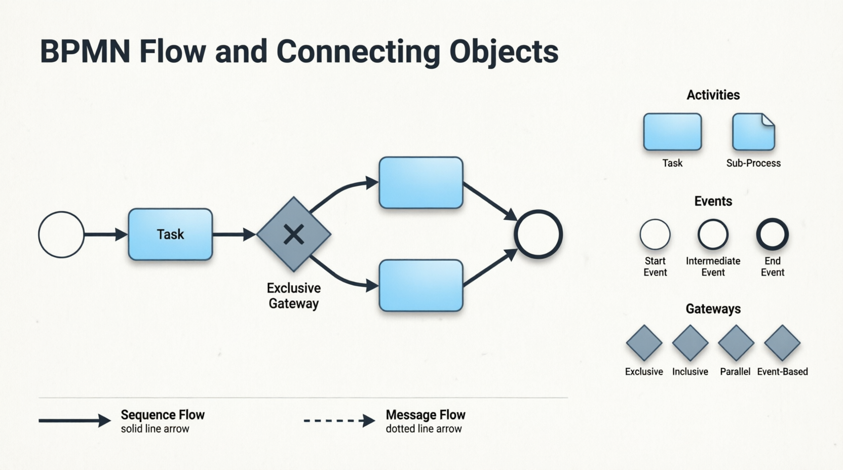
In BPMN, flow elements are the individual components that are connected together to form a complete process flow. These flow elements are connected using connectors, known as connecting objects. When reading a Business Process Diagram (BPD), readers follow the flow of these elements to understand how a business process is executed and completed.
BPMN includes four types of flow elements:
-
Activities (Task and Sub-Process)
-
Events
-
Gateways
In contrast, there are two main types of connecting objects:
-
Sequence Flows
-
Message Flows
Understanding how these elements interact is fundamental to creating clear, executable process models.
Activities: Tasks and Sub-Processes
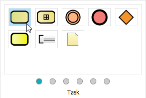
Activities represent the work performed within a business process and are depicted as rounded rectangles with names that describe the work to be done.
Task
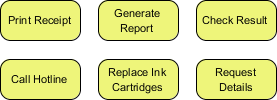
A Task is used to model an atomic unit of work that cannot be broken down further or does not make sense to do so.
Sub-Process
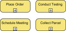
When you want to model a non-atomic, complex piece of work that can be broken down into smaller tasks, you use a Sub-Process. A sub-process can be broken down into another level of detail, which is why it usually contains another BPD that models its details.
Note: The choice between a task and a sub-process is not just about the complexity of the work, but also about the level of detail you need to know. For example, if you are a customer, you probably don’t need to know how your payment is being processed. However, if you are the shop owner, the details of how a customer’s payment is processed are very important.
Events: Start, Intermediate, and End
Events represent occurrences that can affect a business process and can be either internal or external. They are shown as circles with icons to indicate the type of trigger.
Three Types of Events:
| Event Type | Purpose | Visual Indicator |
|---|---|---|
| Start Event | Shows where the process begins | Single thin circle |
| Intermediate Event | Models events that occur during the process; can be attached to activities or connected by flow objects | Double circle |
| End Event | Indicates where the process ends | Single thick circle |
Each event can have a specified trigger condition (e.g., message, timer, error).
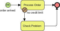
Example: The process starts when an order is received and ends when the order is processed or a problem is identified (e.g., no remaining credit limit).
Gateways: Controlling Process Flow
Gateways, shown as diamond shapes, control the flow of a business process by making decisions based on internal or external conditions. For example, a discount may only be offered to a VIP buyer.
Types of Gateways:
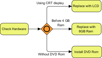
1. Data-Based Exclusive Gateway
Controls the process flow based on given process data. Each outgoing flow corresponds to a condition, and only one flow is taken based on the satisfied condition.

2. Inclusive Gateway
Creates parallel paths where all outgoing flows with positive results are taken, resulting in the execution of multiple flows if multiple conditions are satisfied.
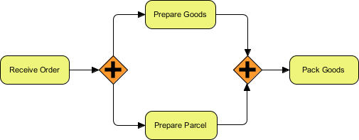
3. Parallel Gateway
Models the execution of parallel flows without checking any conditions, meaning all outgoing flows are executed at the same time.
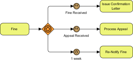
4. Event-Based Gateway
Models alternative paths based on events. For example, waiting for a “Yes” or “No” reply to determine which path to take. The gateway is followed by two connected intermediate events with message triggers. When one event is triggered, its flow is taken, and all other events and their subsequent flows become invalid.
Connecting Objects: Sequence Flows and Message Flows
Sequence Flows
A Sequence Flow is used to connect flow elements. It is shown as a solid line with an arrowhead and indicates the order of the flow elements.

Rule: You can only use a sequence flow to connect flow elements within the same pool, either within the same lane or across lanes in the same pool.
Message Flows
In BPMN, communication between pools is achieved through messages. A Message Flow is used to show the flow of messages between pools or between flow elements in different pools. A message flow is shown as a dotted line with an arrowhead.
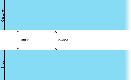
Examples of messages: faxes, telephone calls, emails, letters, notices, and commands.
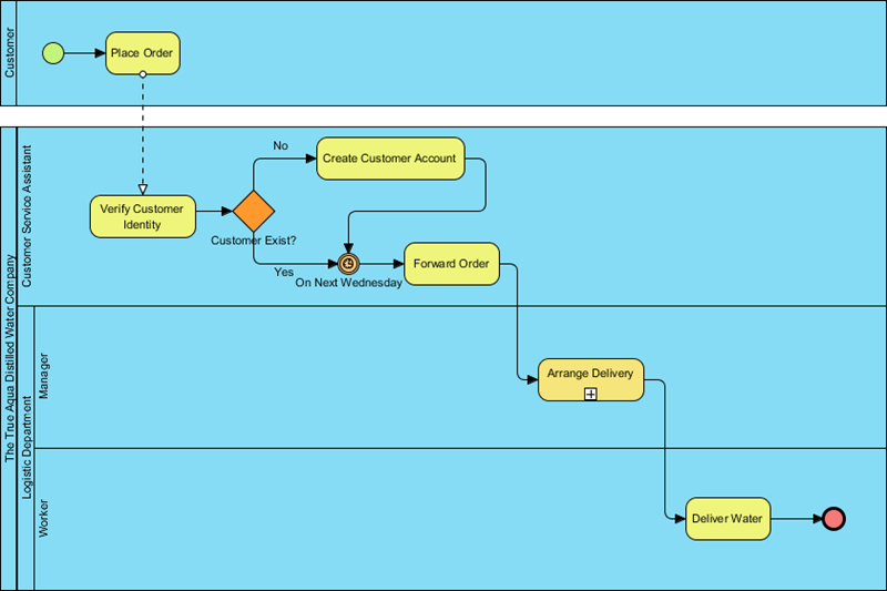
Case Study: True Aqua Distilled Water Company
Continuing from Part II, we now draw the process flow for the distilled water order process.
Step-by-Step Process Modeling:
-
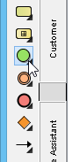
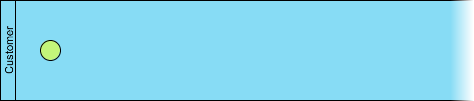
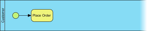
Create Start Event: The process starts when a customer places an order. Create a start event in the Customer pool.
-
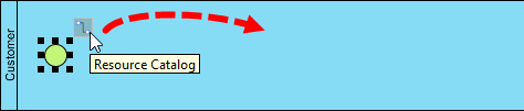
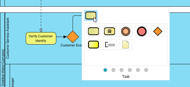
Add “Place Order” Task: Use the Resource Catalog to create a task after the start event.
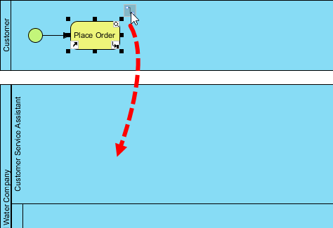
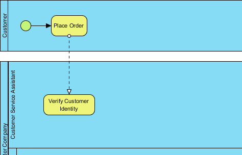
-
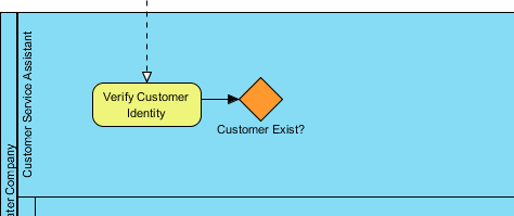
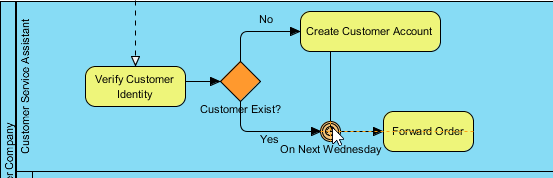
Add “Verify Customer Identity” Task: Create this task in the Customer Service Assistant lane. Note: A message flow is automatically created between pools.
-
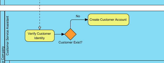
Add Gateway for Customer Check: Use a gateway to model the decision: does the customer exist?
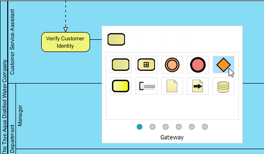
-
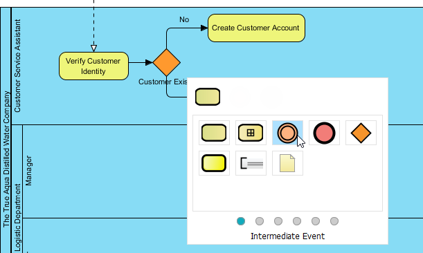
Model “No” Path (New Customer): Create task Create Customer Account with sequence flow labeled No.
-
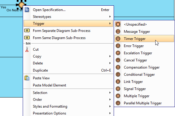
Model “Yes” Path (Existing Customer): Use an Intermediate Timer Event to wait until Wednesday.
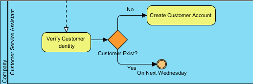
Set the trigger: Right-click → Trigger > Timer Trigger
-
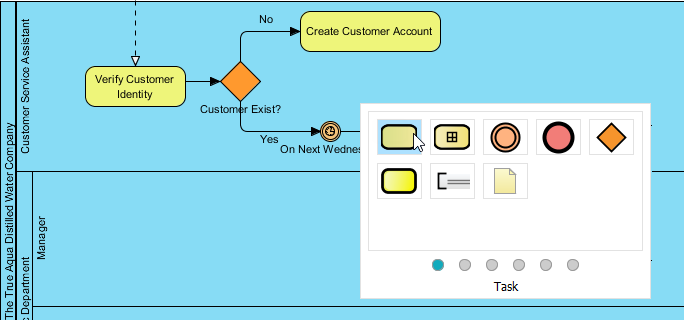
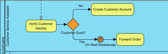
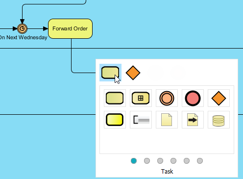
Add “Forward Order” Task: After the timer event, create the task to forward the order.
-
Connect Account Creation to Timer: Add a sequence flow from Create Customer Account to the On Next Wednesday intermediate event to ensure new customers also wait until Wednesday.
-
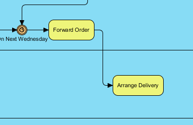
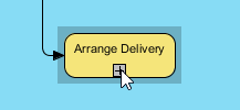
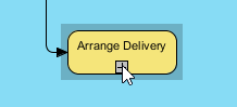
Add “Arrange Delivery” Task in Logistics: Create this task in the Manager lane.
-
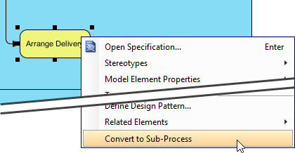
Convert to Sub-Process: Since arranging delivery involves multiple sub-activities, convert the task to a sub-process.
-
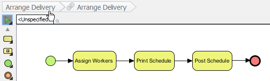
Model Sub-Process Details: Click the + icon to drill down. Create three tasks: Assign Workers, Print Schedule, and Post Schedule.

Tip: To reuse pools/lanes from the parent diagram, right-click the BPD background → Add Pools/Lanes from Parent Diagram… → Select Manager lane.
-
Return to Parent Diagram: Click the shortcut link at the top.
-
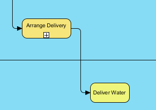
Keep Sub-Process Collapsed: Optionally show content via the + icon, but keeping it collapsed maintains diagram clarity.
-
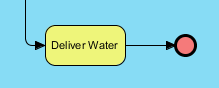
Add “Deliver Water” Task: Create this task in the Worker lane after Arrange Delivery.
-
Add End Event: Complete the process with an end event.
-
Final Diagram:
Best Practices and Key Concepts
✅ Modeling Guidelines
| Concept | Best Practice |
|---|---|
| Task vs. Sub-Process | Use sub-processes when you need to hide complexity or reuse logic; keep parent diagrams focused on high-level flow. |
| Gateway Selection | Choose gateway types based on decision logic: Exclusive (one path), Inclusive (multiple possible paths), Parallel (all paths), Event-Based (wait for trigger). |
| Sequence vs. Message Flow | Sequence flows connect elements within a pool; message flows connect elements across pools. |
| Event Triggers | Always specify trigger types (message, timer, error) for intermediate and start events to clarify process behavior. |
| Diagram Clarity | Collapse sub-processes in parent diagrams; use descriptive names for all elements; avoid crossing flows where possible. |
🔑 Key BPMN Concepts Recap
-
Flow Elements: Activities, Events, Gateways—the “verbs” of your process.
-
Connecting Objects: Sequence Flows (order), Message Flows (communication)—the “connectors”.
-
Pools and Lanes: Represent participants and organizational roles (covered in Part II).
-
Hierarchy: Sub-processes enable modular, multi-level process modeling.
-
Executable Models: Well-defined triggers and conditions allow BPMN diagrams to be executed by workflow engines.
Reference List
- Part III – Flow and Connecting Objects (PDF Download): Downloadable PDF version of this BPMN tutorial covering flow elements, connecting objects, and the True Aqua case study.
- Visual Paradigm Enterprise Edition: Full-featured BPMN modeling suite with advanced collaboration, simulation, and code generation capabilities.
- Visual Paradigm Professional Edition: Comprehensive BPMN tool for business analysts and process architects with diagramming and documentation features.
- Visual Paradigm Standard Edition: Essential BPMN modeling capabilities for small teams and individual practitioners.
- Visual Paradigm Modeler Edition: Lightweight BPMN editor focused on diagram creation and basic process documentation.
- Official BPMN Specification (bpmn.org): The authoritative source for BPMN 2.0 standard documentation, notation reference, and compliance guidelines.
- Part I – Introduction to BPMN: Foundational tutorial covering BPMN history, core notation, and basic diagram elements.
- Part II – Swimlanes: Tutorial on modeling organizational responsibilities using pools, lanes, and participant interactions.
- Part IV – Data and Artifacts: Advanced tutorial on modeling data objects, data stores, annotations, and process artifacts in BPMN.
This guide synthesizes the Visual Paradigm BPMN tutorial series to provide a practical, reference-ready resource for business analysts, process architects, and BPM practitioners. All images and conceptual content are retained from the original source for educational clarity
This post is also available in Deutsch, Español, فارسی, Français, English, Bahasa Indonesia, 日本語, Polski, Portuguese, Ру́сский, Việt Nam, 简体中文 and 繁體中文.