


Introduction to BPMN
Business Process Model and Notation (BPMN) is a standardized graphical representation for specifying business processes in a workflow. Developing workflows involves capturing all relevant information about a process:
-
Who is involved in the process
-
What they’re responsible for
-
How tasks are handed off between participants
-
Which tasks are manual and which are automated
BPMN provides a visual language that bridges the gap between business stakeholders and technical developers, making processes easier to understand, analyze, and improve.
BPMN is Hard to Learn?
Many critics of BPMN 2.0 complain that it is too complicated to learn, particularly due to the numerous notations to memorize. However, what critics often fail to mention is that most processes do not require the modeler to know the entire specification. In fact, most models use only a handful of the most common process elements.
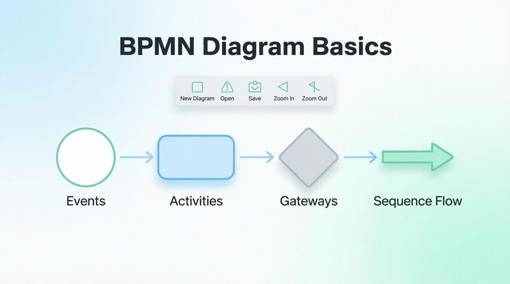
The Four Core BPMN Elements
BPMN consists of only 3 basic types of elements plus a flow connector element:
-
Events – Represent something that happens (start, intermediate, or end points in a process)
-
Activities – Represent work or tasks performed within a process
-
Gateways – Control the flow of the process (decisions, merges, forks, joins)
-
Flow – Sequence Flow (the black lines with arrows) connects the other three elements together
While each of these elements has variants that add complexity, mastering these four fundamentals allows you to model the vast majority of business processes effectively.
Drawing a Business Process Diagram with Visual Paradigm
Follow this step-by-step tutorial to create a BPMN diagram using Visual Paradigm.
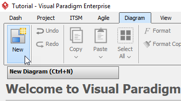
Step 1: Create a New Diagram
Select Diagram > New from the toolbar.
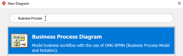
Step 2: Select Business Process Diagram
In the New Diagram window, select Business Process Diagram, then click Next. You can use the Search bar above to filter results.
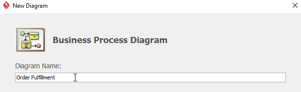
Step 3: Name Your Diagram
Name the diagram then click OK. In this tutorial, we name the diagram Order Fulfillment.
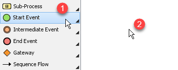
Step 4: Add a Start Event
To create a start event, select Start Event, then click the location where you want the start event to be placed.
Step 5: Convert to Message Start Event
We want a message start event instead of a plain start event. Right-click the start event > Trigger > Message Trigger to make it a Message Start Event.
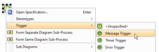
Don’t forget to name the message start event by double-clicking it. We name it Order Received.
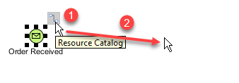
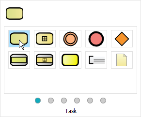
Step 6: Add a Task
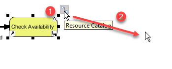
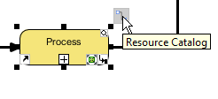
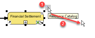
To create a task after Order Received, select Order Received, click and hold the Resource Catalog button, then drag the cursor to the desired location and release. In the popup window, select Task. Double-click the task to rename it. We name this task Check Availability.
Step 7: Add a Gateway
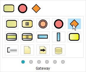
We would like to have a gateway after Check Availability. Select Check Availability, click and hold the Resource Catalog, drag to the desired location and release. Select Gateway from the popup window. Name the gateway Article Available.
Step 8: Create the “Yes” Path
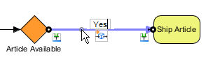
Create a task named Ship Article after Article Available using the method similar to Step 6. Double-click the sequence flow between Article Available and Ship Article and rename it to Yes.
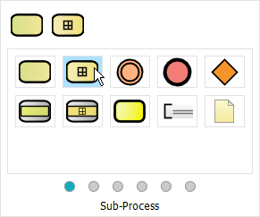
Step 9: Create the “No” Path with Sub-Process
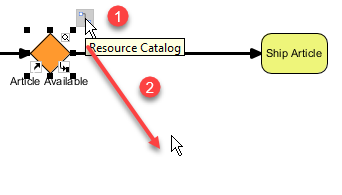
Create a sub-process named Procurement after Article Available with the sequence flow called No. Click Article Available, click and hold Resource Catalog, drag to desired location and release. Select Sub-Process from the popup window, double-click to rename to Procurement. Name the sequence flow No.
Step 10: Connect Sub-Process to Next Task
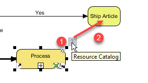
Select Procurement, click and hold Resource Catalog, drag to Ship Article and release to create a flow between Procurement and Ship Article.
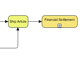
Step 11: Add Financial Settlement Sub-Process
Create a sub-process after Ship Article named Financial Settlement using the method from Step 9.
Step 12: Add Error Intermediate Event
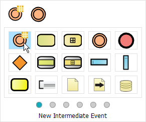
We would like to create an error intermediate event named Deliverable on Procurement. Click Procurement > Resource Catalog, then select New Intermediate Event from the popup window.
Step 13: Configure Error Trigger
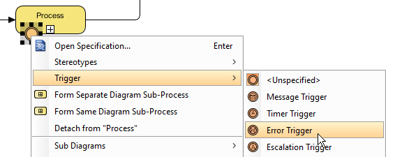
Right-click the newly created intermediate event > Trigger > Error Trigger. Name the error intermediate event Deliverable.
Step 14: Add Escalation Intermediate Event
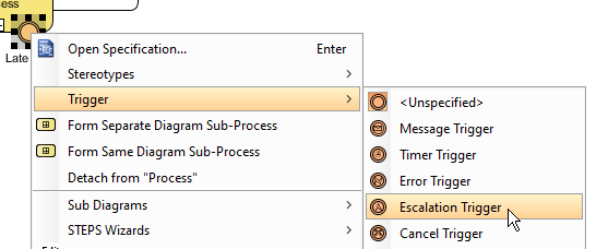
Create an escalated intermediate event called Late Delivery using the same method as Steps 12 and 13. However, when repeating Step 13, select Escalation Trigger instead.
Step 15: Continue Building the Diagram
You can create more tasks using Step 6. You should see something like this after creating more tasks:
Step 16: Add End Event
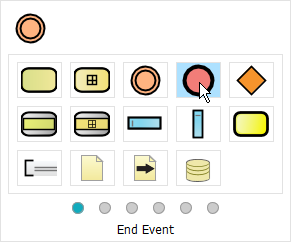
Now we can create an end event after Financial Settlement. Select Financial Settlement, click and hold Resource Catalog, drag to desired location and release, then select End Event from the popup window.
Step 17: Add Additional End Events
Create two more end events, one after both Inform Customer and Remove Article from Catalogue, repeating Step 16.
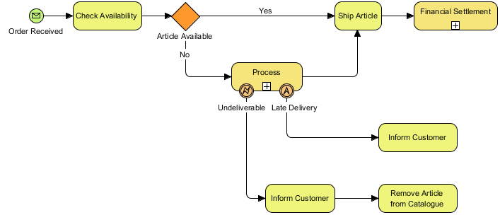
Step 18: Final Diagram
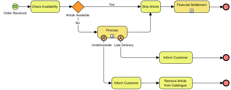
You should now see a diagram similar to this:
Key BPMN Concepts Reference
| Element Type | Purpose | Common Variants |
|---|---|---|
| Events | Mark start, intermediate points, or end of a process | Start, End, Intermediate; Message, Timer, Error, Escalation triggers |
| Activities | Represent work performed | Task, Sub-Process, Call Activity, Looping Activities |
| Gateways | Control process flow decisions | Exclusive (XOR), Parallel (AND), Inclusive (OR), Event-Based |
| Sequence Flow | Connect elements showing order of execution | Default flow, Conditional flow, Message flow (for cross-pool communication) |
Reference List
How to Draw BPMN Diagram?: A comprehensive tutorial introducing the fundamentals of BPMN and providing a step-by-step guide to creating business process diagrams using Visual Paradigm.
BPMN is hard to learn?: Addresses common concerns about BPMN complexity, explaining that most processes only require mastery of four core elements: Events, Activities, Gateways, and Flow.
Drawing a business process diagram: A practical, illustrated walkthrough demonstrating how to build an Order Fulfillment BPMN diagram from start to finish using Visual Paradigm’s intuitive interface.
BPMN diagramming simplifies complex workflows by focusing on four core elements—Events, Activities, Gateways, and Flow—allowing teams to visually map who does what, when, and how tasks connect; with tools like Visual Paradigm, creating professional process models becomes an accessible, step-by-step process requiring only fundamental notation knowledge.
Comprehensive Guide: How to Draw BPMN Diagrams
Introduction to BPMN
Business Process Model and Notation (BPMN) is a standardized graphical notation for modeling business processes. Developing workflows using BPMN involves capturing all relevant information about a process:
-
Who is involved in the process
-
What they’re responsible for
-
How tasks are handed off between participants
-
Which tasks are manual and which are automated
BPMN Is Hard to Learn?
Many critics of BPMN 2.0 complain that BPMN is too complicated to learn, particularly due to the many notations to be memorized. However, what critics often fail to mention is that most processes do not require the modeler to know the entire specification. In fact, most models don’t use more than a handful of the most common process elements.
The Four Core BPMN Elements
BPMN consists of only 3 basic types of elements plus 1 flow connector element:
-
Events – Represent something that happens (start, intermediate, or end of a process). Depicted as circles.
-
Activities – Represent work performed in a process (tasks or sub-processes). Depicted as rounded rectangles.
-
Gateways – Represent decision points or branching logic. Depicted as diamonds.
-
Flow (Sequence Flow) – The black lines with arrows that connect Events, Activities, and Gateways to show process order.
While each of these elements has variants that add complexity, mastering these four fundamentals enables you to model most business processes effectively.
Drawing a Business Process Diagram with Visual Paradigm
Follow this step-by-step tutorial to create an Order Fulfillment BPMN diagram.
Step 1: Create a New Diagram
Select Diagram > New from the toolbar.
Step 2: Select Business Process Diagram Type
In the New Diagram window, select Business Process Diagram, then click Next. Use the Search bar to filter results if needed.
Step 3: Name Your Diagram
Name the diagram (e.g., Order Fulfillment) then click OK.
Step 4: Add a Start Event
Select Start Event, then click the canvas where you want the start event placed.
Step 5: Convert to Message Start Event
Right-click the start event > Trigger > Message Trigger to convert it to a Message Start Event. Double-click to rename it Order Received.
Step 6: Add a Task
Select Order Received, click and hold the Resource Catalog button, drag to the desired location, and release. In the popup, select Task. Double-click to rename it Check Availability.
Step 7: Add a Gateway
Select Check Availability, use the Resource Catalog to drag and drop a Gateway. Name it Article Available.
Step 8: Create the “Yes” Path
Create a task named Ship Article after Article Available. Double-click the sequence flow between them and label it Yes.
Step 9: Create the “No” Path with Sub-Process
From Article Available, use the Resource Catalog to add a Sub-Process. Name it Procurement and label the connecting flow No.
Step 10: Connect Sub-Process to Next Task
Select Procurement, use the Resource Catalog to drag a flow to Ship Article, connecting the two elements.
Step 11: Add Financial Settlement Sub-Process
After Ship Article, create another sub-process named Financial Settlement using the same method as Step 9.
Step 12: Add an Error Intermediate Event
Click Procurement > Resource Catalog, then select New Intermediate Event.
Step 13: Configure Error Trigger
Right-click the new intermediate event > Trigger > Error Trigger. Name it Deliverable.
Step 14: Add an Escalation Intermediate Event
Repeat Steps 12–13, but select Escalation Trigger instead. Name it Late Delivery.
Step 15: Expand with Additional Tasks
Continue adding tasks using the method from Step 6. Your diagram should begin to resemble this:
Step 16: Add an End Event
Select Financial Settlement, use the Resource Catalog to drag and drop an End Event.
Step 17: Add Final End Events
Create two more end events after Inform Customer and Remove Article from Catalogue using the same method.
Step 18: Final Diagram
Your completed BPMN diagram should look similar to this:
Key Concepts & Best Practices
| Concept | Description |
|---|---|
| Start/End Events | Define process boundaries; use appropriate triggers (message, timer, error) |
| Tasks vs. Sub-Processes | Use tasks for atomic actions; sub-processes for complex, reusable logic |
| Exclusive Gateways | Model decision points with mutually exclusive paths (XOR logic) |
| Sequence Flows | Always label conditional flows (e.g., Yes/No) for clarity |
| Intermediate Events | Attach to activities to model exceptions, escalations, or timers |
| Resource Catalog | Visual Paradigm’s drag-and-drop tool for rapid element placement |
Reference List
- How to Draw BPMN Diagram?: A step-by-step tutorial demonstrating how to create a business process diagram using Visual Paradigm, covering diagram creation, element placement, and workflow modeling.
- BPMN is hard to learn?: An explanatory section addressing common misconceptions about BPMN complexity, emphasizing that most processes only require mastery of four core element types.
- Drawing a business process diagram: A practical, illustrated walkthrough of building an Order Fulfillment process diagram, including events, tasks, gateways, sub-processes, and exception handling.
Note: All images and instructional content are sourced from Visual Paradigm’s official tutorial. For the most current version of this guide, please visit the original article.
This post is also available in Deutsch, Español, فارسی, Français, English, Bahasa Indonesia, 日本語, Polski, Portuguese, Ру́сский, Việt Nam, 简体中文 and 繁體中文.