


What is a C4 Container Diagram?
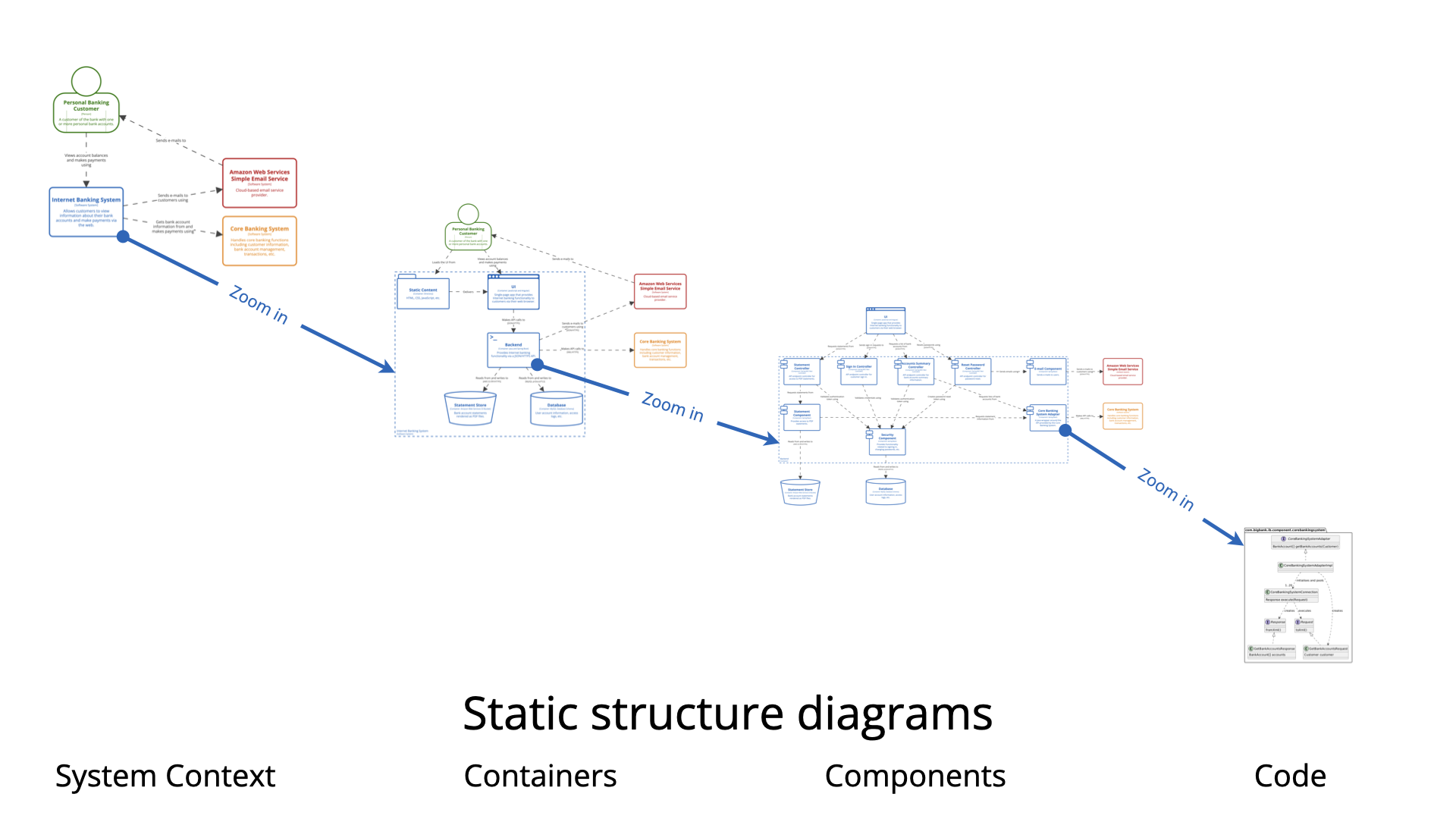
The Container diagram is Level 2 in Simon Brown’s C4 model. It zooms into a single software system (defined at Level 1 – System Context) to show:
-
The high-level shape of the architecture inside your system boundary.
-
Major deployable/runnable units called containers.
-
Technology choices for each container.
-
How containers interact with each other and with external actors/systems.
Important clarification: A “container” in C4 is not necessarily a Docker container. It is any separately deployable/run-time unit that executes code or stores data. Examples:
-
Web application / Single-Page Application (SPA)
-
Mobile app
-
Server-side API / microservice
-
Database (schema)
-
File storage (S3 bucket, file system folder)
-
Message broker / queue (when modeled explicitly)
-
Desktop / CLI application
-
Batch process / scheduled job
The diagram remains high-level — no internal class or code details (that’s Level 3 Components or Level 4 Code).
When to Create a Container Diagram
Create (and maintain) a Container diagram when:
-
You have completed (or at least sketched) the System Context diagram and need to answer: “What are the major building blocks inside our system?”
-
Onboarding new developers, architects, or operations staff — they need to quickly understand technology stack and high-level responsibilities.
-
Making significant technology or architectural decisions (monolith → microservices, adding mobile app, choosing database, introducing message queues, cloud migration).
-
Documenting for audits, compliance, security reviews, or incident response (helps show attack surface, data flows).
-
You want “architecture as code” that lives in the repository and evolves with the system.
-
Most teams stop here — Simon Brown himself notes that System Context + Container diagrams are sufficient for the majority of software teams. Only go deeper (Components/Code) when complexity inside a container justifies it.
Skip or defer if:
-
The system is extremely simple (one process + database).
-
You’re doing very early ideation and only need the big-picture context.
Why Use Container Diagrams? (Key Benefits)
-
Clarity for different audiences
Developers see technologies and integration points.
Ops/infra teams see deployable units and communication paths.
Architects see responsibility boundaries and tech debt risks.
Managers see a technology-neutral-enough yet concrete view. -
Avoids the “one big diagram” problem
Prevents dumping everything (users + infra + classes + cloud icons) into a single overloaded picture. -
Highlights key decisions
Clearly exposes choices like SPA + API + relational DB vs. server-side rendering + NoSQL, or synchronous vs. event-driven. -
Communication & collaboration
Acts as a shared map during design sessions, incident post-mortems, threat modeling, and roadmapping. -
Living documentation
When written in PlantUML / Structurizr DSL / similar → versioned in Git, auto-regenerated on CI, always up-to-date.
How to Create a Great Container Diagram (Step-by-Step + Best Practices)
-
Start from Level 1
Copy Persons + external Software Systems from the Context diagram — they become actors that interact with your containers. -
Draw the System Boundary
UseSystem_Boundaryin PlantUML to clearly scope “inside our system”. -
Identify Containers
Ask: What are the separately runnable/deployable things that deliver the system’s functionality?
Common patterns:-
Web SPA ↔ API backend ↔ Database
-
Mobile app ↔ Backend-for-frontend (BFF) ↔ Shared services
-
Microservices with message broker
-
Legacy monolith + new API layer
-
-
Add Technology & Brief Description
Every container should show: name, technology, short purpose.
Keep descriptions < 15 words. -
Define Interactions (Relationships)
Show direction + protocol + intent (e.g., “JSON/HTTPS”, “Reads from and writes to”, “Publishes to”, “Consumes from”).
Use verbs on relationships. -
Best Practices
-
Keep it readable — aim for < 10–12 containers. If more → create focused views (e.g., “API subsystem containers”).
-
Be consistent — same layout direction (top-down/left-right), same level of detail.
-
Use icons/sprites — add visual pop (PlantUML supports devicons, font-awesome, etc.).
-
Legend & key — enable automatic legend in PlantUML.
-
Avoid clutter — omit queues/topics if they don’t add value; label protocols on arrows instead.
-
Version & store as code — commit .puml files to repo.
-
Audience tailoring — one version for devs (detailed tech), lighter version for stakeholders.
-
PlantUML Example – Classic Internet Banking System (Big Bank plc style)
Here is a clean, production-grade example using the official C4-PlantUML library.
@startuml
!include https://raw.githubusercontent.com/plantuml-stdlib/C4-PlantUML/master/C4_Container.puml

' Optional: add nice icons (from tupadr3 sprites)
!include https://raw.githubusercontent.com/tupadr3/plantuml-icon-font-sprites/master/devicons/angular.puml
!include https://raw.githubusercontent.com/tupadr3/plantuml-icon-font-sprites/master/devicons/java.puml
!include https://raw.githubusercontent.com/tupadr3/plantuml-icon-font-sprites/master/devicons/postgresql.puml
!include https://raw.githubusercontent.com/tupadr3/plantuml-icon-font-sprites/master/devicons/android.puml

title Container Diagram: Internet Banking System

Person(customer, "Personal Banking Customer", "A customer of Big Bank plc")

System_Boundary(c1, "Internet Banking System") {
    Container(spa, "Single-Page App", "JavaScript & Angular", "Provides all the internet banking functionality to customers via their web browser", $sprite="angular")
    Container(mobile, "Mobile App", "Android/iOS (React Native)", "Limited internet banking functionality", $sprite="android")
    Container(api, "API Application", "Java & Spring Boot", "Provides Internet Banking functionality via API", $sprite="java")
    ContainerDb_Ext(db, "Banking Database", "PostgreSQL", "Stores user preferences, cached data, sessions (core accounts/transactions remain in mainframe)", $sprite="postgresql")
}

System_Ext(core, "Core Banking System", "Mainframe system – existing")
System_Ext(email, "Email System", "Sends emails (e.g. AWS SES)")

Rel(customer, spa, "Uses", "HTTPS")
Rel(customer, mobile, "Uses", "HTTPS")

Rel(spa, api, "Calls", "JSON/HTTPS")
Rel(mobile, api, "Calls", "JSON/HTTPS")

Rel(api, db, "Reads from and writes to", "JDBC/SQL")
Rel(api, core, "Uses", "JSON/HTTPS")
Rel(api, email, "Sends email using", "HTTPS")

LAYOUT_WITH_LEGEND()
LAYOUT_TOP_DOWN()

@enduml
This renders a clean diagram with:
-
System boundary
-
Technology labels
-
Sprites/icons
-
Clear relationships
-
Legend
You can paste it directly into the PlantUML online server or any compatible IDE/editor.
Use this structure as a template — replace elements with your own system’s names, technologies, and flows. For more advanced styling (themes, custom colors), check the C4-PlantUML GitHub samples.
Happy diagramming — and remember: the goal is effective communication, not UML perfection!
C4 Container Diagram Resource
- Ultimate Guide to C4 Model Visualization Using Visual Paradigm’s AI Tools: This guide explains how to leverage AI-powered tools to automate and enhance C4 model visualization for faster software architecture design.
- Leveraging Visual Paradigm’s AI C4 Studio for Streamlined Architecture Documentation: This article details using an AI-enhanced studio to create clean, scalable, and maintainable software architecture documentation.
- The Ultimate Guide to C4-PlantUML Studio: Revolutionizing Software Architecture Design: This resource explores combining AI-driven automation, the C4 model’s clarity, and PlantUML’s flexibility into a single powerful tool.
- A Comprehensive Guide to Visual Paradigm’s AI-Powered C4 PlantUML Studio: This guide describes a purpose-built tool released in late 2025 that transforms natural language prompts into layered C4 diagrams.
- C4-PlantUML Studio | AI-Powered C4 Diagram Generator: This feature overview highlights an AI-driven tool designed to generate C4 software architecture diagrams from simple text descriptions.
- Generating and Modifying C4 Component Diagrams with Visual Paradigm AI Chatbot: This tutorial demonstrates using an AI-powered chatbot to iteratively create and refine component-level architecture for complex systems.
- AI-Powered C4 Diagram Generator: Core Levels and Supporting Views: This page explains how the AI generator supports the four core levels of the C4 model—Context, Container, Component, and Deployment—to provide comprehensive documentation.
- AI Diagram Generator: Complete C4 Model Support Release: This update details the integration of AI-powered features for the automated creation of hierarchical C4 model diagrams.
- C4 Model AI Generator: Automating the Full Modeling Lifecycle: This resource highlights how a specialized AI chatbot uses conversational prompts to ensure consistency across architecture documentation for DevOps teams.
- Comprehensive Review: Generic AI Chatbots vs. Visual Paradigm’s C4 Tools: This comparison explains why specialized tools like the C4 PlantUML Studio provide more structured and professional-grade results than general-purpose language models.
This post is also available in Deutsch, Español, فارسی, Français, English, Bahasa Indonesia, 日本語, Polski, Portuguese, Ру́сский, Việt Nam, 简体中文 and 繁體中文.