


The C4 model, created by Simon Brown, is a simple, hierarchical, and developer-friendly way to visualize software architecture. It uses four levels of abstraction (hence “C4”) to describe a system from the highest-level overview down to code-level details:
- System Context (Level 1) – The big picture: the system and its users/external dependencies.
- Containers (Level 2) – High-level technology choices and responsibilities.
- Components (Level 3) – Major logical building blocks inside a container.
- Code (Level 4) – Optional class-level or code-structure details.
It is supported by three additional diagram types:
- System Landscape
- Dynamic
- Deployment
The model is notation-independent (you can use any diagramming tool) and focuses on clarity, consistency, and audience-appropriate detail. It is widely adopted because it avoids “big ball of mud” architecture diagrams and scales from whiteboard sketches to automated documentation.
For this targeted case study, we use the canonical example from the official C4 website: Internet Banking System for the fictional “Big Bank plc”. The business goal is to let personal customers view their accounts and make payments online while integrating with the bank’s existing core systems.
We will walk through every level with:
- Purpose and audience
- Key elements + responsibilities
- Relationships
- A ready-to-use PlantUML C4 diagram (PlantUML supports C4 syntax and renders beautifully in most Markdown viewers)
- Rationale and key decisions
- How the diagram helps stakeholders
Step 1: Define Scope & Create the System Context Diagram (Level 1)
Purpose: Show how the new Internet Banking System fits into the world. Audience: business stakeholders, non-technical people, new team members.
Elements (from the official example):
- Personal Banking Customer (Person) – A customer with one or more personal bank accounts.
- Internet Banking System (Software System) – The new system we are building.
- Core Banking System (Software System, existing) – Mainframe that handles customer data, accounts, and transactions.
- Email System (Software System, external) – Amazon Web Services Simple Email Service (AWS SES) for sending confirmations.
Relationships:
- Customer → uses → Internet Banking System (to view accounts and make payments)
- Internet Banking System → uses → Core Banking System (for account data & payments)
- Internet Banking System → sends email via → Email System
Here is the PlantUML C4 Context diagram:
")
@startuml
!include https://static.visual-paradigm.com/plantuml-stdlib/C4-PlantUML/master/C4_Context.puml

LAYOUT_TOP_DOWN()
LAYOUT_WITH_LEGEND()

title System Context Diagram (Level 1) for Internet Banking System

Person(customer, "Personal Banking Customer", "A customer with one or more personal bank accounts.")
System(internet_banking_system, "Internet Banking System", "The new system for viewing accounts and making payments.")
System(core_banking_system, "Core Banking System", "Existing mainframe handling customer data, accounts, and transactions.")
System_Ext(email_system, "Email System", "Amazon Web Services Simple Email Service (AWS SES) for sending confirmations.")

Rel(customer, internet_banking_system, "Uses")
Rel(internet_banking_system, core_banking_system, "Uses")
Rel(internet_banking_system, email_system, "Sends email via")

Lay_D(customer, internet_banking_system)
Lay_D(internet_banking_system, core_banking_system)
Lay_U(email_system, internet_banking_system)
@endumlRationale & value: This single diagram immediately answers “What are we building and who does it talk to?” It prevents scope creep by making external dependencies explicit. Business stakeholders love it because there is no technology detail yet.
Step 2: Container Diagram (Level 2)
Purpose: Zoom into the Internet Banking System and show the major deployable/runnable units (containers) and their technology choices. Audience: architects, lead developers, operations.
Containers inside Internet Banking System:
- Single-Page Application (Web Browser – JavaScript + Angular) – Full internet banking UI.
- Mobile App (Mobile device – iOS/Android native or React Native) – Limited functionality for on-the-go use.
- API Application (Server-side – Java + Spring Boot) – JSON/HTTPS API used by both front-ends.
- Database (Relational DB – PostgreSQL) – Stores session data, user preferences, cached account summaries (core data stays in the mainframe).
Key relationships (same external systems as Level 1):
- SPA & Mobile App → call → API Application
- API Application ↔ Database
- API Application → Core Banking System & Email System
PlantUML C4 Container diagram:
@startuml
!include https://static.visual-paradigm.com/plantuml-stdlib/C4-PlantUML/master/C4_Container.puml
!include https://raw.githubusercontent.com/tupadr3/plantuml-icon-font-sprites/master/devicons/angular.puml
!include https://raw.githubusercontent.com/tupadr3/plantuml-icon-font-sprites/master/devicons/java.puml
!include https://raw.githubusercontent.com/tupadr3/plantuml-icon-font-sprites/master/devicons/postgresql.puml

LAYOUT_TOP_DOWN()
LAYOUT_WITH_LEGEND()

title C4 Container Diagram for Internet Banking System

Person(customer, "Personal Banking Customer", "A customer with one or more personal bank accounts.")

System_Boundary(internet_banking_system, "Internet Banking System", "The new system for viewing accounts and making payments.") {
Container(spa, "Single-Page Application", "JavaScript + Angular", "Full internet banking UI", $sprite="angular")
Container(mobile_app, "Mobile App", "iOS/Android (React Native)", "Limited functionality for on-the-go use", $sprite="react")
Container(api_app, "API Application", "Java + Spring Boot", "JSON/HTTPS API used by both front-ends", $sprite="java")
ContainerDb(database, "Database", "PostgreSQL", "Stores session data, user preferences, cached account summaries", $sprite="postgresql")
}

System(core_banking_system, "Core Banking System", "Existing mainframe handling customer data, accounts, and transactions.")
System_Ext(email_system, "Email System", "Amazon Web Services Simple Email Service (AWS SES) for sending confirmations.")

' Relationships
Rel(customer, spa, "Uses", "HTTPS")
Rel(customer, mobile_app, "Uses", "HTTPS")
Rel(spa, api_app, "Calls", "JSON/HTTPS")
Rel(mobile_app, api_app, "Calls", "JSON/HTTPS")
Rel(api_app, database, "Reads from and writes to", "JDBC/SQL")
Rel(api_app, core_banking_system, "Queries / Updates", "JSON/HTTPS")
Rel(api_app, email_system, "Sends email via", "HTTPS")

' Layout hints (optional – helps PlantUML arrange elements better)
Lay_D(customer, internet_banking_system)
Lay_D(internet_banking_system, core_banking_system)
Lay_U(email_system, internet_banking_system)

@enduml
Rationale: We chose a modern SPA + API backend pattern for web, a native mobile app for performance, and kept the database lightweight (most data lives in the legacy mainframe). This diagram is the single source of truth for high-level technology decisions and helps DevOps plan infrastructure.
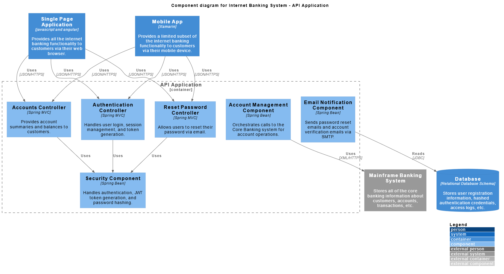
Step 3: Component Diagram (Level 3)
Purpose: Zoom into one container (usually the most complex one – the API Application) and show its major logical components. Audience: development teams.
Example: Components inside the API Application:
- Accounts Controller (Spring MVC)
- Authentication Controller
- Reset Password Controller
- Security Component (handles auth, JWT, etc.)
- Account Management Component (orchestrates calls to Core Banking)
- Email Notification Component
PlantUML C4 Component diagram (focused on the API Application):
@startuml
!include https://static.visual-paradigm.com/plantuml-stdlib/C4-PlantUML/master/C4_Component.puml

LAYOUT_WITH_LEGEND()

title Component diagram for Internet Banking System - API Application

Container(spa, "Single Page Application", "javascript and angular", "Provides all the internet banking functionality to customers via their web browser.")
Container(ma, "Mobile App", "Xamarin", "Provides a limited subset of the internet banking functionality to customers via their mobile device.")
ContainerDb(db, "Database", "Relational Database Schema", "Stores user registration information, hashed authentication credentials, access logs, etc.")
System_Ext(mbs, "Mainframe Banking System", "Stores all of the core banking information about customers, accounts, transactions, etc.")

Container_Boundary(api, "API Application") {
    Component(accounts, "Accounts Controller", "Spring MVC", "Provides account summaries and balances to customers.")
    Component(auth, "Authentication Controller", "Spring MVC", "Handles user login, session management, and token generation.")
    Component(reset, "Reset Password Controller", "Spring MVC", "Allows users to reset their password via email.")
    Component(security, "Security Component", "Spring Bean", "Handles authentication, JWT token generation, and password hashing.")
    Component(accountmgmt, "Account Management Component", "Spring Bean", "Orchestrates calls to the Core Banking system for account operations.")
    Component(email, "Email Notification Component", "Spring Bean", "Sends password reset emails and account verification emails via SMTP.")

    Rel(accounts, security, "Uses")
    Rel(auth, security, "Uses")
    Rel(reset, security, "Uses")
    Rel(accountmgmt, mbs, "Uses", "XML/HTTPS")
    Rel(email, db, "Reads", "JDBC")
}

Rel(spa, accounts, "Uses", "JSON/HTTPS")
Rel(spa, auth, "Uses", "JSON/HTTPS")
Rel(spa, reset, "Uses", "JSON/HTTPS")
Rel(ma, accounts, "Uses", "JSON/HTTPS")
Rel(ma, auth, "Uses", "JSON/HTTPS")
Rel(ma, reset, "Uses", "JSON/HTTPS")
@enduml
Rationale: This level shows how responsibilities are split (separation of concerns) and makes onboarding new developers much faster. You only draw component diagrams for containers that are complex enough to warrant it.
Step 4: Code Diagram (Level 4) – Optional
Purpose: Show the internal structure of a single component (class diagram, sequence, etc.). Audience: developers working on that code.
Example for the Authentication Controller component – a simple UML class diagram in PlantUML:
@startuml
classDiagram

skinparam {
roundcorner 8
ArrowColor #444444
ArrowFontColor #444444
BorderColor #444444

Class {
BorderColor #1A237E
BackgroundColor #E8EAF6
FontColor #1A237E
}
}

class "AuthenticationController" {
+login(credentials)
+refreshToken()
}

class "JwtTokenProvider" {
+generateToken(user)
+validateToken(token)
}

class "UserRepository" {
+findByUsername()
}

AuthenticationController ..> JwtTokenProvider : "uses"
AuthenticationController ..> UserRepository : "uses"
@enduml
In real projects you often skip Level 4 and point to the actual source code instead.
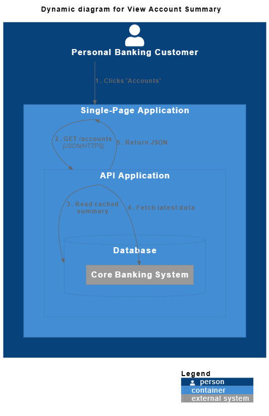
Step 5: Supporting Diagrams
Dynamic Diagram (example: “View Account Summary” flow)
@startuml
!include https://static.visual-paradigm.com/plantuml-stdlib/C4-PlantUML/master/C4_Deployment.puml

title Dynamic diagram for View Account Summary

Person(customer, "Personal Banking Customer") {
Container(spa, "Single-Page Application") {
Container(api, "API Application") {
ContainerDb(db, "Database") {
System_Ext(coreBanking, "Core Banking System")
}
}
}
}

Rel(customer, spa, "1. Clicks 'Accounts'", "")
Rel(spa, api, "2. GET /accounts", "JSON/HTTPS")
Rel(api, db, "3. Read cached summary", "")
Rel(api, coreBanking, "4. Fetch latest data", "")
Rel(api, spa, "5. Return JSON", "")

SHOW_LEGEND()
@endumlDeployment Diagram (high-level physical mapping):
@startuml
!include https://static.visual-paradigm.com/plantuml-stdlib/C4-PlantUML/master/C4_Deployment.puml

title Deployment Diagram for Internet Banking System

Deployment_Node(aws, "Amazon Web Services", "Cloud") {
Deployment_Node(ec2, "EC2 Auto-Scaling Group", "Linux") {
Container(api, "API Application", "Java Spring Boot")
}
Deployment_Node(rds, "RDS", "PostgreSQL") {
ContainerDb(db, "Database")
}
}

Deployment_Node(customerDevice, "Customer's Device", "Web/Mobile") {
Container(spa, "Single-Page Application")
Container(mobile, "Mobile App")
}

System_Ext(coreBanking, "Core Banking System (on-prem mainframe)")

Rel(spa, api, "Makes API calls to", "HTTPS")
Rel(mobile, api, "Makes API calls to", "HTTPS")
Rel_U(api, spa, "Delivers to the customer's web browser")
Rel_U(api, mobile, "Delivers to the mobile app")

SHOW_LEGEND()
@enduml
How to Use This Case Study in Practice
- Start with a workshop: draw Context on a whiteboard.
- Iterate to Containers and Components using PlantUML C4.
- Keep diagrams in the code repo (as code!) so they stay up-to-date.
- Generate living documentation automatically.
This exact Internet Banking System example is the official reference created by Simon Brown and is used in thousands of organizations worldwide. By following these steps you now have a complete, production-ready architecture description that anyone—from CEO to new junior developer—can understand at the right level of detail.
C4 Diagram Articles
- Ultimate Guide to C4 Model Visualization Using Visual Paradigm’s AI Tools: This guide explains how to leverage AI-powered tools to automate and enhance C4 model visualization for faster software architecture design.
- Leveraging Visual Paradigm’s AI C4 Studio for Streamlined Architecture Documentation: This article details using an AI-enhanced studio to create clean, scalable, and maintainable software architecture documentation.
- The Ultimate Guide to C4-PlantUML Studio: Revolutionizing Software Architecture Design: This resource explores combining AI-driven automation, the C4 model’s clarity, and PlantUML’s flexibility into a single powerful tool.
- A Comprehensive Guide to Visual Paradigm’s AI-Powered C4 PlantUML Studio: This guide describes a purpose-built tool released in late 2025 that transforms natural language prompts into layered C4 diagrams.
- C4-PlantUML Studio | AI-Powered C4 Diagram Generator: This feature overview highlights an AI-driven tool designed to generate C4 software architecture diagrams from simple text descriptions.
- Generating and Modifying C4 Component Diagrams with Visual Paradigm AI Chatbot: This tutorial demonstrates using an AI-powered chatbot to iteratively create and refine component-level architecture for complex systems.
- AI-Powered C4 Diagram Generator: Core Levels and Supporting Views: This page explains how the AI generator supports the four core levels of the C4 model—Context, Container, Component, and Deployment—to provide comprehensive documentation.
- AI Diagram Generator: Complete C4 Model Support Release: This update details the integration of AI-powered features for the automated creation of hierarchical C4 model diagrams.
- C4 Model AI Generator: Automating the Full Modeling Lifecycle: This resource highlights how a specialized AI chatbot uses conversational prompts to ensure consistency across architecture documentation for DevOps teams.
- Comprehensive Review: Generic AI Chatbots vs. Visual Paradigm’s C4 Tools: This comparison explains why specialized tools like the C4 PlantUML Studio provide more structured and professional-grade results than general-purpose language models.
This post is also available in Deutsch, Español, فارسی, Français, English, Bahasa Indonesia, 日本語, Polski, Portuguese, Ру́сский, Việt Nam, 简体中文 and 繁體中文.