


1. Executive Summary
This case study presents a formal, production-grade UML state machine design for an Automated Order Lifecycle System, built to manage the full journey of a customer order—from placement to delivery or cancellation—while ensuring data integrity, inventory control, and user experience constraints.
The solution leverages UML State Machine Diagrams to model complex workflows with nested states, conditional transitions, and explicit actions. We integrate modern AI-assisted tools like Visual Paradigm’s AI UML Diagram Generator to accelerate and enhance the design process, ensuring accuracy, scalability, and alignment with software engineering best practices.
2. Key Concepts in UML State Machine Modeling
🔹 What is a UML State Machine?
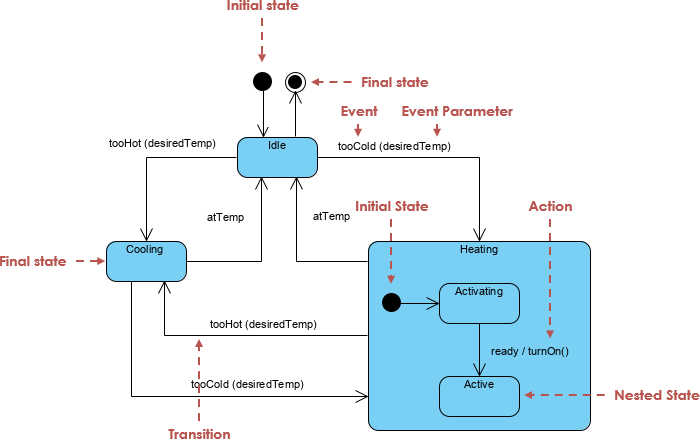
A UML State Machine (also known as a Statechart Diagram) models the dynamic behavior of a system by defining how objects transition between states in response to events (triggers), with actions, guards, and transitions.
🔹 Core Elements in This Diagram:
| Element | Description |
|---|---|
| States | Represent phases in the order lifecycle (e.g., Idle, Paid, Delivered). |
| Transitions | Arrows showing movement from one state to another. |
| Triggers | Events that cause transitions (e.g., ConfirmPayment, Timeout). |
| Actions | Operations performed during entry, exit, or on transition (e.g., check_system, cancel_reservation). |
| Entry/Exit Actions | Executed when entering/exiting a state (e.g., entry / check_system). |
| Sub-states (Composite States) | Nested states within a superstate (e.g., Paid → Processing → Shipped → Delivered). |
| Terminal States | Final states (Delivered, Cancelled) that end the lifecycle. |
| Concurrent States | Not used here—this is a single-path lifecycle. |
| Deep History vs. Shallow History | Not needed; only one active path per order. |
✅ Why State Machines?
They provide a formal, visual way to capture complex business logic, prevent invalid transitions, and enforce constraints—critical for systems like order management where consistency and traceability matter.
3. Problem Breakdown: Functional Requirements
Let’s map each requirement into UML constructs.
| Requirement | UML Representation |
|---|---|
| System starts in Idle state; perform self-check on startup | entry / check_system on Idle |
User places order → PaymentPending |
Idle --> PaymentPending : PlaceOrder |
On ConfirmPayment → Paid |
PaymentPending --> Paid : ConfirmPayment |
On Timeout → Cancelled |
PaymentPending --> Cancelled : Timeout / cancel_reservation |
Paid state has nested sub-states: Processing → Shipped → Delivered |
Nested composite state with [*] initial pseudostate |
Delivered and Cancelled are terminal states |
Both end with --> [*] (final state) |
Orders in Paid or beyond cannot be edited |
Enforced via state constraints (not directly in diagram but implied in logic) |
4. Complete UML State Machine Diagram (with PlantUML)

@startuml
[*] --> Idle
state Idle {
  Idle : entry / check_system
}
Idle --> PaymentPending : PlaceOrder
PaymentPending --> Paid : ConfirmPayment
PaymentPending --> Cancelled : Timeout / cancel_reservation

state Paid {
  [*] --> Processing
  Processing --> Shipped : LabelGenerated
  Shipped --> Delivered : CustomerSigned
}
Delivered --> [*]
Cancelled --> [*]

note right of Paid : Order cannot be edited \nonce in this state.
@enduml
🖼️ Visual Output (as generated by PlantUML):
A clean, hierarchical diagram showing:
Initial state (
[*])Idle → PaymentPending → (Paid → Processing → Shipped → Delivered) and (Paid → Cancelled)
Actions on transitions and entry
Terminal states marked with
[*]
5. In-Depth State Behavior Analysis
🟦 Idle State
-
Entry Action:
check_system– Validates database connectivity. -
Trigger:
PlaceOrder– Initiates order creation. -
Exit Condition: Order ID generated; move to
PaymentPending.
🟨 PaymentPending State
-
Guarded Transition: No explicit guard in this case, but timeout is implied.
-
Critical Behavior:
-
If
ConfirmPaymentreceived → move toPaid. -
If
Timeoutoccurs (e.g., after 15 minutes) → cancel reservation and move toCancelled.
-
⚠️ Security Insight: This is where inventory locking occurs and must be released in
cancel_reservation, preventing over-allocation.
🟩 Paid State (Composite)
-
Initial Pseudostate:
[*]→Processing -
Internal Transitions:
-
Processing→Shipped: whenLabelGeneratedsignal received (e.g., after label is printed). -
Shipped→Delivered: whenCustomerSignedis confirmed (via tracking or digital signature).
-
✅ Key Advantage of Composite State: The
Paidstate groups multiple sub-states, allowing for:
Clear lifecycle progression
Avoiding duplicate event handling
Better maintainability
6. How to Use Visual Paradigm’s AI UML Diagram Generator
Visual Paradigm (VP) is a powerful UML modeling tool that supports AI-powered diagram generation from natural language. Here’s how to leverage it for this case study.
✅ Step-by-Step Guide: From Text to UML Diagram via AI
Step 1: Prepare the Natural Language Input
Use the problem description as input. Paste the full “Automated Order Lifecycle System” requirements into the AI prompt field.
📝 Prompt Example (Optimized for AI):
Generate a UML State Machine diagram for an automated order lifecycle system with the following states: Idle, PaymentPending, Paid, Processing, Shipped, Delivered, Cancelled.

Transitions:
- Idle → PaymentPending on "PlaceOrder"
- PaymentPending → Paid on "ConfirmPayment"
- PaymentPending → Cancelled on "Timeout" with action "cancel_reservation"
- Paid → Processing (initial state)
- Processing → Shipped on "LabelGenerated"
- Shipped → Delivered on "CustomerSigned"

Actions:
- entry / check_system on Idle
- entry / check_system on Idle

Terminal states: Delivered, Cancelled

Add a note: "Order cannot be edited once in Paid state"

Output: UML State Machine Diagram in standard syntax.
Step 2: Use Visual Paradigm’s AI Diagram Generator
-
Open Visual Paradigm Online or Desktop.
-
Go to “AI” → “Generate Diagram”.
-
Paste the prompt above.
-
Select “State Machine Diagram” as the output type.
-
Click Generate.
💡 AI Output Features:
Automatically identifies states, triggers, actions, and notes.
Suggests proper structure (composite states, initial/pseudostates).
Adds correct syntax (e.g.,
[*],entry / action).Highlights terminal states with
[*].
Step 3: Refine & Export
-
Review: Check if
Paidis correctly shown as a composite state withProcessingas its initial state. -
Add Constraints: Manually add a constraint note:
@{1} Order in Paid or beyond: locked from edits. -
Export Options: Export to PNG, SVG, PDF, or integrate into documentation (Word, Confluence).
7. Real-World Benefits of This Approach
| Benefit | Explanation |
|---|---|
| ✅ Reduced Development Errors | Clear state transitions prevent invalid operations (e.g., editing a delivered order). |
| ✅ Improved Maintainability | Changes to business rules (e.g., extend timeout from 15 to 30 mins) are easier to visualize. |
| ✅ Better Collaboration | Devs, QA, and product owners can align on system behavior using a shared visual language. |
| ✅ Automated Testing Foundation | Each state and transition can be mapped to unit or integration tests. |
| ✅ Scalability | Easy to add new triggers (e.g., RefundRequested, ReturnInitiated) for future extensions. |
8. Example Use Case: Order Flow Execution
Imagine a customer places an order:
| Step | Event | System State | Action Taken |
|---|---|---|---|
| 1 | PlaceOrder |
Idle → PaymentPending |
Start 15-minute payment window |
| 2 | ConfirmPayment |
PaymentPending → Paid |
Reserve inventory; begin Processing |
| 3 | LabelGenerated |
Processing → Shipped |
Print shipping label; notify carrier |
| 4 | CustomerSigned |
Shipped → Delivered |
Mark as delivered; update status in DB |
| 5 | User tries to edit | Delivered state |
Blocked – state is locked |
🔒 Data Integrity Enforced: No changes allowed after
Paidstate.
9. Best Practices for UML State Machine Design
| Practice | Why It Matters |
|---|---|
| Use composite states for complex workflows | Avoids flat, unmanageable state diagrams. |
| Document entry/exit actions clearly | Ensures startup checks and cleanup (e.g., releasing inventory). |
| Define terminal states explicitly | Ensures lifecycle completeness. |
| Use AI tools for rapid prototyping | Speeds up design phase; reduces human error. |
| Pair with event-driven architecture | Aligns well with microservices or event sourcing patterns. |
10. Conclusion: Why This Case Study Works
This Automated Order Lifecycle System demonstrates how UML State Machine Diagrams—when designed with care and supported by AI tools like Visual Paradigm—can:
-
Translate complex business logic into visual, actionable blueprints.
-
Enforce constraints and data integrity.
-
Provide a shared language across teams.
-
Enable automated testing, documentation, and system validation.
🎯 Final Thought:
In modern software development, a well-designed state machine is not just documentation—it’s a contract between business rules and code.
Use AI-powered tools like Visual Paradigm to generate, verify, and evolve these diagrams with confidence.
Ready to automate your next order system? Start with a state machine. 🚀
Articles and resources:
- Mastering State Diagrams with Visual Paradigm AI: A Guide for Automated Toll Systems: This guide demonstrates how to use AI-enhanced state diagrams to model and automate the complex logic required for toll system software.
- Definitive Guide to UML State Machine Diagrams with AI: This resource provides a detailed look at using AI-powered tools to accurately model object behavior with UML state machine diagrams.
- Interactive State Machine Diagram Tool: A specialized web-based tool for creating and editing state machine diagrams that leverages GenAI capabilities for real-time behavior modeling.
- Generating Source Code from State Machines in Visual Paradigm: This technical guide provides instructions on generating implementation code directly from state machine diagrams to execute state-driven logic.
- Visual Paradigm – UML State Machine Diagram Tool: An overview of a cloud-based interface designed for architects to build, edit, and export precision state machine models.
- 3D Printer State Machine: A Comprehensive Step-by-Step Guide: A walkthrough of the state machine concept as applied to 3D printing systems, explaining their operational logic and automation paths.
- State Diagram Quick Tutorial: Master UML State Machines in Minutes: A beginner-friendly tutorial for mastering UML state machines, covering core concepts and modeling techniques within Visual Paradigm.
- Visualizing System Behavior: A Practical Guide to State Diagrams with Examples: An analysis of how state diagrams provide an intuitive visualization to identify potential system issues early in the design process.
- Creating State Machine Diagrams in Visual Paradigm: Official documentation detailing how to design and implement system behavior modeling using state machine diagrams.
- Visual Paradigm AI Suite: A Comprehensive Guide to Intelligent Modeling Tools: This overview details how the platform’s AI Chatbot supports technical modeling, including state machines and other behavioral diagrams, within the modeling environment.
This post is also available in Deutsch, Español, فارسی, Français, English, Bahasa Indonesia, 日本語, Polski, Portuguese, Ру́сский, Việt Nam, 简体中文 and 繁體中文.