


The landscape of software engineering and system design is undergoing a significant transformation due to the integration of artificial intelligence into modeling tools. Specifically, the ability to model dynamic behavior through UML (Unified Modeling Language) has been revolutionized by platforms like Visual Paradigm. By leveraging AI-powered features, teams can now create, refine, and master UML state machine diagrams (often called statecharts) using natural language prompts and intelligent automation. This guide explores how to utilize these advanced tools to eliminate manual drawing efforts and focus on high-level logic for complex object lifecycles.
Understanding UML State Machine Diagrams
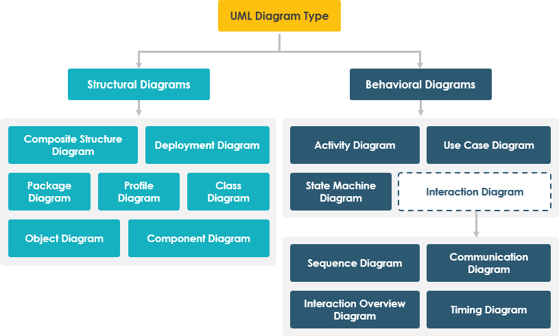
UML state machine diagrams are essential for visualizing how an object, system, or component behaves over time. Unlike static diagrams that show structure, state diagrams illustrate how an entity responds to events by transitioning between discrete states. They are particularly critical for reactive systems—such as user interfaces, embedded devices, protocols, and automated workflows—where the system’s behavior is dependent on its current state and incoming stimuli.
Key Elements of a Statechart
To effectively model behavior, it is important to understand the standard components that Visual Paradigm’s AI will generate based on your descriptions:
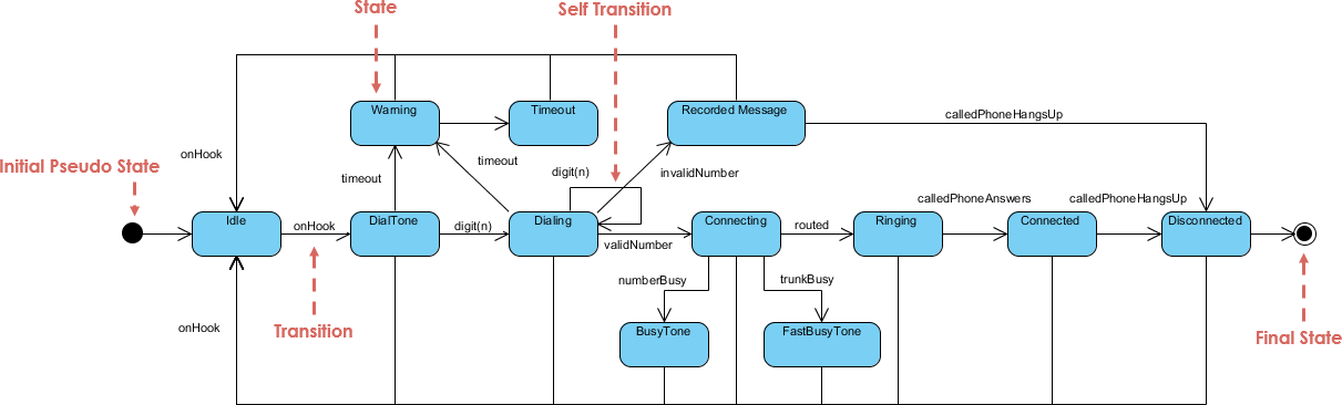
- States: Represented as rounded rectangles, these depict specific conditions or situations (e.g., “Idle,” “Processing,” “Error”).
- Initial State: A solid black circle that marks the starting point of the flow.
- Final State: A solid circle inside a larger circle indicating the process has terminated or completed.
- Transitions: Directed arrows that indicate a change from one state to another.
- Events/Triggers: The external or internal stimuli that cause a transition to occur (e.g., “vehicle detected” or “payment received”).
- Guards: Boolean conditions enclosed in brackets (e.g.,
[payment valid]) that must evaluate to true for the transition to execute. - Actions/Activities: Operations that occur during transitions, or upon entering, exiting, or remaining within a state.
How Visual Paradigm AI Enhances Diagram Creation
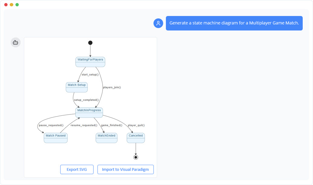
Visual Paradigm’s AI chatbot shifts the workflow from manual drag-and-drop mechanics to conversational design. By accessing tools like the online AI chatbot, users can describe system behavior in plain English, and the engine transforms this into syntactically correct UML diagrams instantly.
The AI handles the heavy lifting of layout organization, ensures proper notation, and even detects logical flaws such as dead-end states or unhandled events. Key capabilities include:
- Text-to-Diagram Generation: Instantly rendering visual models from text descriptions.
- Conversational Editing: Allowing users to refine diagrams with follow-up commands like “Add a guard for invalid input” or “Color error paths red.”
- Logic Validation: The AI can analyze the diagram to suggest improvements or identify unreachable states.
- Code Generation: Converting the visual diagram into implementation code for languages like Java, Python, and C++.
Step-by-Step Workflow: From Text to Diagram
Creating a complex state machine diagram is now a structured, efficient process. Follow this workflow to maximize the potential of Visual Paradigm AI:
1. Access the Tool
Navigate to Visual Paradigm’s online AI interface (such as chat.visual-paradigm.com) and initiate a new diagramming session.
2. Craft a Clear Prompt
The quality of the output depends on the clarity of the input. Describe the system’s behavior comprehensively, specifying key states, triggers, and outcomes. For example:
“Create a state diagram for an automated toll collection system. The system starts in Idle. When a vehicle approaches, it transitions to In Range and reads the license plate. If valid, proceed to Payment Processing. On successful payment, go to Payment Received, generate a receipt, and open the lane. If payment fails or no payment, transition to No Payment then Penalty (apply fine and notify). Reset to Idle after processing.”
3. Generate and Review
Submit the prompt. The AI will produce a diagram with proper UML notation, including substates (e.g., validating the plate) and distinct paths for success and failure.
4. Iterate and Refine
Use conversational prompts to polish the diagram. You might say, “Add a guard [plate valid] on the validation transition” or “Highlight the penalty flow in red.” The tool updates the visual in real-time.
5. Validate and Export
Ask the AI to check for logical errors, such as “Are there any dead-end states?” Once satisfied, export the diagram as a PNG, PDF, or PlantUML file, or generate the corresponding code for development.
Real-World Applications
The versatility of AI-driven state modeling applies to various industries and scenarios:
- Automated Toll Systems: As illustrated in the workflow, AI can model complex flows involving vehicle detection, substates for validation, payment processing, and enforcement actions like penalties. It ensures both normal operations and exception handling are covered.
- Smart Devices (IoT): For a smart thermostat, the diagram might start at “Off,” transitioning to “Heating” or “Cooling” based on temperature events and guards (e.g.,
[temp > target]). - Document Workflows: Modeling the lifecycle of a document from “Draft” to “In Review” (triggered by a submit action) and finally to “Published,” with loops back to “Draft” if changes are requested.
Benefits and Best Practices
Adopting AI for UML state machine diagrams offers speed, accuracy, and accessibility. It lowers the barrier for non-experts while providing reliable design-to-code bridges for engineers.
To get the best results, adhere to these best practices:
- Be Specific: Use structured prompts that clearly define states and conditions.
- Iterate: Treat the process as a conversation. Don’t expect perfection in the first prompt; refine it step-by-step.
- Visual Customization: Ask the AI to adjust colors and legends to distinguish between happy paths and error flows.
- Validate Logic: Leverage the AI’s analytical capabilities to explain transitions and catch missing links.
Visual Paradigm‘s AI tools represent a major leap forward, turning complex behavioral modeling into an intuitive process that empowers teams to design faster and more reliably.
The following articles and resources provide detailed information on using AI-powered tools to create, refine, and master UML state machine diagrams within the Visual Paradigm platform:
-
Mastering State Diagrams with Visual Paradigm AI: A Guide for Automated Toll Systems: This guide demonstrates how to utilize AI-enhanced state diagrams to model and automate the complex behaviors of an automated toll system.
-
AI-Powered UML Chatbot State Diagrams: This article explores the ways artificial intelligence improves the creation and interpretation of UML state diagrams specifically for the development of chatbot systems.
-
Definitive Guide to UML State Machine Diagrams with AI: This comprehensive resource provides a detailed guide on using AI-enhanced modeling tools to visualize object behavior through UML state machine diagrams.
-
Interactive State Machine Diagram Tool: This web-based platform allows teams to create and edit state machine diagrams in real time with generative AI support for faster software engineering workflows.
-
Visual Paradigm – UML State Machine Diagram Tool: This interactive online tool provides a dedicated interface for creating, editing, and exporting detailed UML state machine diagrams for modern software design.
-
AI Chatbot for Diagram and Model Generation: This AI-powered assistant enables users to generate various models, including state diagrams, through natural language interaction and simple text prompts.
This post is also available in Deutsch, Español, فارسی, Français, English, Bahasa Indonesia, 日本語, Polski, Portuguese, Ру́сский, Việt Nam, 简体中文 and 繁體中文.