


What is Unified Modeling Language (UML)?
Unified Modeling Language (UML) is a standardized modeling language that consists of an integrated set of diagrams. It was developed to assist system and software developers in specifying, visualizing, constructing, and documenting the artifacts of software systems. UML is also applicable to business modeling and other non-software systems. It represents a collection of best engineering practices proven successful in modeling large and complex systems.
")
UML plays a crucial role in object-oriented software development and the overall software development process. It primarily uses graphical notations to express software project designs, enabling project teams to communicate effectively, explore potential designs, and validate architectural decisions.
In this tutorial, we’ll cover UML’s origins, history, importance, an overview of its diagrams (with examples), a glossary of key terms, popular books, and how modern tools like Visual Paradigm’s AI features can enhance productivity in UML modeling.
The Origin of UML
The goal of UML is to provide a standard notation usable by all object-oriented methods, integrating the best elements from precursor notations. UML supports a broad range of applications, including distributed systems, analysis, system design, and deployment.
UML resulted from the unification of several methodologies:
- Object Modeling Technique (OMT) by James Rumbaugh (1991): Best for analysis and data-intensive systems.
- Booch Method by Grady Booch (1994): Excellent for design and implementation, though its notation (cloud shapes) was less tidy.
- Object-Oriented Software Engineering (OOSE) by Ivar Jacobson (1992): Introduced Use Cases, a technique for understanding system behavior.
In 1994, Rumbaugh joined Booch at Rational Corp. to merge their ideas into a “Unified Method.” By 1995, Jacobson joined, incorporating Use Cases, leading to the Unified Modeling Language (UML). The trio—Rumbaugh, Booch, and Jacobson—are known as the “Three Amigos.”
UML was also influenced by other notations, such as those from Mellor and Shlaer (1998), Coad and Yourdon (1995), Wirfs-Brock (1990), and Martin and Odell (1992). It introduced new concepts like extension mechanisms and a constraint language.
History of UML
UML’s development was catalyzed by the Object Management Group (OMG):
- In 1996, OMG issued a Request for Proposal (RFP), prompting organizations to collaborate on a joint response.
- Rational formed the UML Partners consortium, including companies like Digital Equipment Corp, HP, i-Logix, IntelliCorp, IBM, ICON Computing, MCI Systemhouse, Microsoft, Oracle, Rational Software, TI, and Unisys.
- This produced UML 1.0 in January 1997, a well-defined, expressive language.
- Additional responses from IBM, ObjecTime, Platinum Technology, Ptech, Taskon, Reich Technologies, and Softeam led to UML 1.1, adopted by OMG in fall 1997.
- UML evolved through versions 1.1 to 1.5, then to UML 2.0 series, with the current version being 2.5 as of 2025.
Why UML?
As software’s strategic value grows, industries seek techniques to automate production, improve quality, reduce costs, and shorten time-to-market. These include component technology, visual programming, patterns, and frameworks. Businesses need ways to manage system complexity, addressing issues like physical distribution, concurrency, replication, security, load balancing, and fault tolerance—exacerbated by web development.
UML responds to these needs with primary design goals (as summarized by Page-Jones in Fundamental Object-Oriented Design in UML):
- Provide a ready-to-use, expressive visual modeling language for developing and exchanging meaningful models.
- Offer extensibility and specialization mechanisms.
- Be independent of programming languages and processes.
- Provide a formal basis for understanding the language.
- Encourage growth in the OO tools market.
- Support higher-level concepts like collaborations, frameworks, patterns, and components.
- Integrate best practices.
UML – An Overview
UML offers multiple diagrams to view systems from different perspectives, catering to stakeholders like analysts, designers, coders, testers, QA, customers, and technical authors. Each requires varying detail levels.
UML 2 diagrams fall into two categories:
Structure Diagrams
These show the static structure of the system, its parts, and relationships. There are seven types:
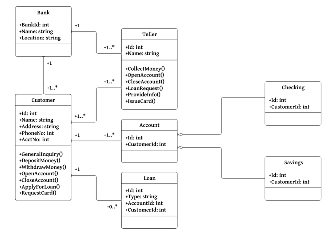
- Class Diagram: Describes object types and static relationships (associations, inheritance, aggregation).
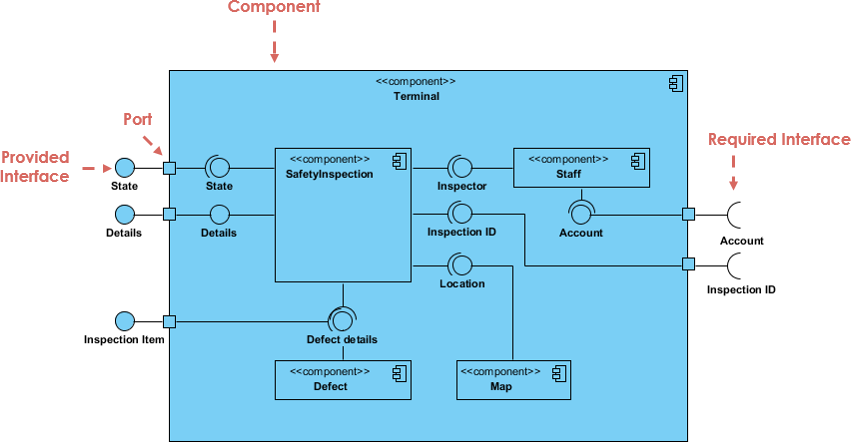
- Component Diagram: Depicts how components form larger systems, including architectures and dependencies.
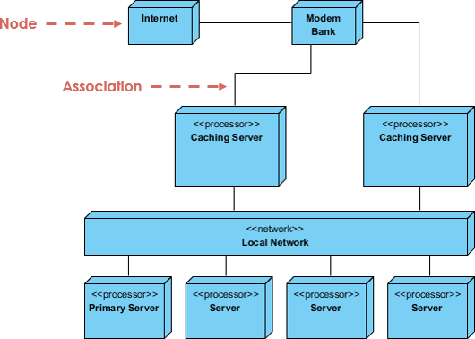
- Deployment Diagram: Models physical deployment of artifacts to hardware.
- Object Diagram: Shows instances and data values at a specific time, like a snapshot of a class diagram.
- Package Diagram: Displays packages and dependencies for multi-layered views.
- Composite Structure Diagram: Shows internal class structure and collaborations.
- Profile Diagram: Defines domain-specific stereotypes and relationships.
Behavior Diagrams
These depict dynamic behavior over time. There are seven types:
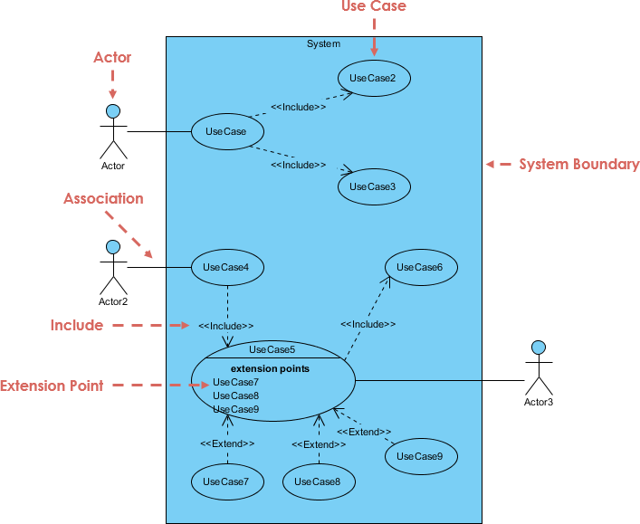
- Use Case Diagram: Models functional requirements, actors, and system responses.
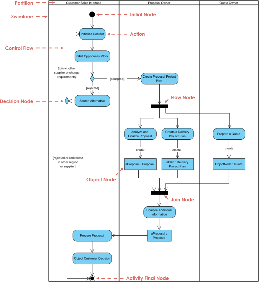
- Activity Diagram: Represents workflows with steps, decisions, and concurrency.
- State Machine Diagram: Describes object states, transitions, and events.
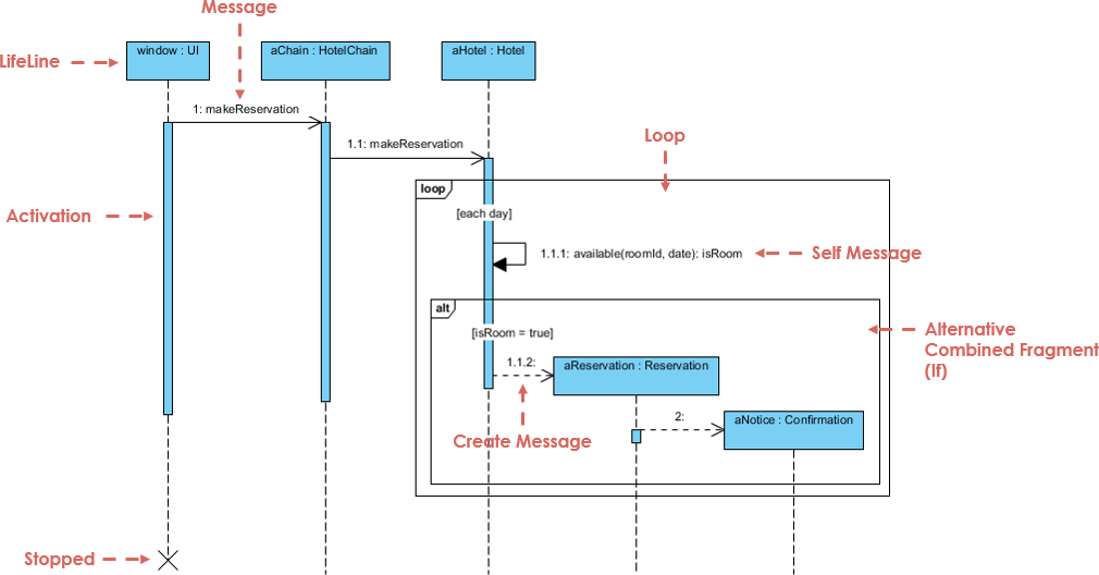
- Sequence Diagram: Shows object interactions in time sequence.
- Communication Diagram: Focuses on object collaborations, less on timing.
- Interaction Overview Diagram: Provides a high-level view of interactions.
- Timing Diagram: Shows object behavior over time, with reversed axes from sequence diagrams.
UML Glossary and Terms
- Abstract Class: A class never instantiated.
- Actor: Initiates system events.
- Activity: A step in an activity diagram.
- Activity Diagram: Flowchart-like diagram for processes.
- Aggregation: “Part-of” relationship.
- Artifacts: Outputs of design steps.
- Association: Connection between model elements.
- Association Class: Adds info to an association.
- Attributes: Object characteristics.
- Base Class: Inherited from in generalization.
- Branch: Decision point in activity diagrams.
- Class: Category of similar objects.
- Class Diagram: Shows classes and relationships.
- Classifier: Element with attributes/operations (e.g., classes, interfaces).
- Collaboration: Message-passing relation in communication diagrams.
- Communication Diagram: Emphasizes object roles.
- Component: Deployable code unit.
- Component Diagram: Shows components/interfaces.
- Concept: Noun/abstract idea in domain models.
- Construction Phase: Main building phase in RUP.
- Dependence: One classifier knows another’s structure.
- Deployment Diagram: Shows processors.
- Domain: System’s relevant universe.
- Elaboration Phase: Planning iterations.
- Element: Any model item.
- Encapsulation: Private data in objects.
- Event: Triggers state changes.
- Final State: Diagram completion point.
- Fork: Starts parallel threads.
- Generalization: Inheritance relationship.
- GoF: Gang of Four design patterns.
- High Cohesion: Class focuses on related functions.
- Initial State: Diagram starting point.
- Instance: Object from a class.
- Interface: Behavior contract.
- Iteration: Mini-project adding functionality.
- Join: Synchronizes parallel threads.
- Low Coupling: Minimal class dependencies.
- Member: Attribute or operation.
- Merge: Combines control paths.
- Message: Object request.
- Method: Object function.
- Model: Central UML artifact.
- Multiplicity: Quantity relationships.
- Navigability: Awareness in relationships.
- Notation: Rules for diagrams.
- Note: Explanatory text.
- Object: Instance or diagram participant.
- Package: Grouped elements.
- Package Diagram: Shows packages/dependencies.
- Pattern: Reusable solution.
- Parameter: Operation argument.
- Polymorphism: Same message, different implementations.
- Private/Protected/Public: Visibility levels.
- Processor: Deployment target.
- Reading Direction Arrow: Relationship direction.
- Realization: Provides an interface.
- Role: Actor description.
- Sequence Diagram: Time-based interactions.
- State: System condition.
- State Diagram: States and transitions.
- Static: Shared/single instance modifier.
- Stereotype: Custom UML dialect.
- Subclass: Inherits from base class.
- Swimlane: Responsibility areas in activity diagrams.
- Time Boxing: Fixed-time iterations.
- Transition: Control/state change.
- Transition Phase: User rollout.
- UML: Unified Modeling Language.
- Use Case: System action.
- Use Case Diagram: Actors and use cases.
- Visibility: Access modifiers.
- Workflow: Activities for a result.
Popular UML Books
- UML Distilled: A Brief Guide to the Standard Object Modeling Language by Martin Fowler.
- UML 2 and the Unified Process: Practical Object-Oriented Analysis and Design by Jim Arlow and Ila Neustadt.
- Learning UML 2.0 by Russ Miles and Kim Hamilton.
- Building Web Applications with UML by Jim Conallen.
- The Unified Modeling Language Reference Manual by James Rumbaugh et al.
- The Elements of UML 2.0 Style by Scott W. Ambler.
- UML for Java Programmers by Robert C. Martin.
- Schaum’s Outline of UML by Simon Bennett et al.
- The Unified Modeling Language User Guide by Grady Booch et al.
- UML 2 Certification Guide: Fundamental and Intermediate Exams by Tim Weilkiens and Bernd Oestereich.
- Fundamentals of Object-Oriented Design in UML by Meilir Page-Jones.
- Applying Use Case Driven Object Modeling with UML: An Annotated E-Commerce Example by Doug Rosenberg and Kendall Scott.
- Designing Flexible Object Oriented Systems With UML by Charles Richter.
- Use Case Driven Object Modeling with UML by Doug Rosenberg and Kendall Scott.
- Systems Analysis and Design with UML Version 2.0: An Object-Oriented Approach by Alan Dennis et al.
- UML 2.0 in a Nutshell by Dan Pilone and Neil Pitman.
- Object-Oriented Analysis and Design with Applications by Grady Booch et al.
- UML Explained by Kendall Scott.
- Design Patterns: Elements of Reusable Object-Oriented Software by Erich Gamma et al. (GoF).
- The Object Primer: Agile Model-Driven Development with UML 2.0 by Scott W. Ambler.
Leveraging Visual Paradigm’s AI Features to Boost Team Productivity
In 2025, tools like Visual Paradigm have integrated advanced AI features to streamline UML modeling, leveraging new technologies such as natural language processing and machine learning. These features automate repetitive tasks, suggest improvements, and enable collaborative refinement, significantly boosting team productivity by reducing manual effort and accelerating iterations.
Key AI Features in Visual Paradigm
- AI Diagram Generator: Converts text descriptions into structured UML diagrams, interpreting intent and suggesting relationships.
- AI Chatbot: Allows conversational commands to generate, refine, and analyze diagrams without manual dragging/dropping.
- AI Use Case Diagram Refinement Tool: Automatically adds ‘include’ and ‘extend’ relationships to enhance clarity.
- AI Textual Analysis: Generates development plans and timelines from requirements.
- Other Specialized Tools: Includes AI for decision tables, tree diagrams, and backlog planning.
Why Use AI in UML Now?
AI democratizes modeling, allowing non-experts to contribute while experts focus on high-level design. It handles complexity in large systems, ensures consistency, and integrates with agile workflows for faster feedback. With real-time collaboration in tools like Visual Paradigm, teams can iterate diagrams during meetings, reducing errors and time-to-market.
Examples of Boosting Productivity
- Generating a Class Diagram: Input a text like “A banking system with User class having name and account, associated with Account class having balance and transactions.” AI generates the diagram, suggests aggregations, and refines via chatbot (e.g., “Add inheritance for SavingsAccount”). This saves hours of manual drawing for a team brainstorming designs.
- Refining Use Cases: For a e-commerce project, describe scenarios in text. AI refines the Use Case Diagram by auto-adding extensions like “Handle Payment Failure.” Teams can then chat: “Add actor for Admin,” instantly updating the model for review.
- Creating Development Plans: From UML artifacts, AI generates timelines and backlogs, integrating with Jira via Agilien. A team can analyze a Sequence Diagram and get an AI-planned sprint, improving coordination and productivity in distributed teams.
By adopting these AI tools, teams can focus on innovation rather than tedium, making UML more accessible and efficient in modern software development. For hands-on experience, try Visual Paradigm’s free Community Edition.
This post is also available in Deutsch, Español, فارسی, Français, English, Bahasa Indonesia, 日本語, Polski, Portuguese, Ру́сский, Việt Nam, 简体中文 and 繁體中文.