


Introduction
Unified Modeling Language (UML) serves as a powerful tool in the realm of software design, offering a graphical language to model the intricate structure and behavior of object-oriented systems. Among its various diagram types, UML class diagrams stand out as fundamental blueprints for visualizing the internal makeup of classes and the relationships that bind them.
Classes: The Building Blocks
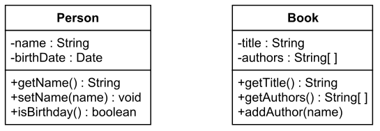
A UML class diagram is composed of rectangles representing individual classes, each divided into three essential parts:
- Class Name: Identifies the name of the class, providing a clear reference point.
- Fields: Specifies the names and types of fields within the class.
- Methods: Outlines the names, return types, and parameters of the methods associated with the class.
For instance, consider a “Person” class with private fields like “name” and “birthDate,” and public methods such as “getName,” “setName,” and “isBirthday.” Meanwhile, a “Book” class may include private fields like “title” and “authors” along with public methods like “getTitle,” “getAuthors,” and “addAuthor.”
Utilizing Relationships
In the real-world development of software, classes often interact with each other through objects and methods. UML class diagrams use relationships to depict these interactions, ranging from weaker dependencies to stronger associations:
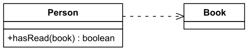
- Dependency: Occurs when an object of one class uses an object of another in a method’s code. This is expressed as a dependency relationship.
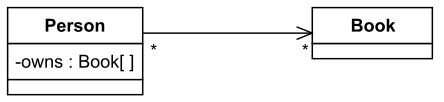
- Unidirectional Association: Represents the storage of one object within a field of another. For instance, a “Person” owning a “Book” might be depicted.
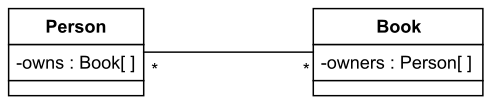
- Bidirectional Association: Both objects store each other in their fields, indicating a mutual relationship.
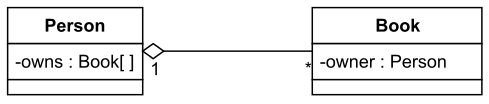
- Aggregation: Describes ownership, where one object has or owns another. For example, a “Person” owning a collection of “Book” objects.
- Composition: An extension of aggregation, where the lifetimes of the objects are closely aligned. In this scenario, a “Person” owning an electronic book exemplifies composition.

Inheritance Relationships
In UML, inheritance relationships mirror those found in Java, providing a mechanism for code reuse and structure extension:
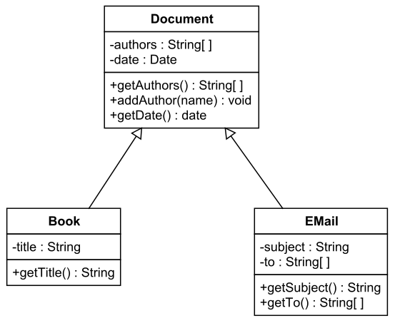
- Generalization: Signifies a class extending another. For example, a “Book” class extending a “Document” class, inheriting and possibly modifying its fields and methods.
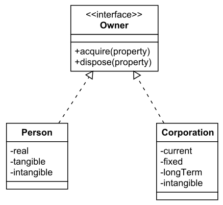
- Realization: Denotes a class implementing an interface. In this context, the “Person” and “Corporation” classes might implement an “Owner” interface with methods for acquiring and disposing of property.
Conclusion
UML class diagrams provide a crucial foundation for understanding and visualizing the intricacies of object-oriented systems in software design. By encapsulating classes, fields, methods, and relationships, these diagrams serve as indispensable tools for developers to communicate, design, and document complex systems.
The representation of classes with their attributes and behaviors allows for a clear and concise overview of the internal structure of software components. The inclusion of relationships, ranging from dependencies to associations, ensures a comprehensive depiction of how classes interact and collaborate in real-world scenarios.
Furthermore, the incorporation of inheritance relationships mirrors established programming paradigms, such as those found in Java, facilitating code reuse and structure extension. Whether through generalization or realization, these relationships enhance the flexibility and modularity of software systems.
As software development continues to evolve, UML class diagrams remain a timeless and valuable asset. Their ability to convey the essence of object-oriented design not only aids in the development phase but also serves as a robust documentation tool, fostering collaboration among development teams.
In essence, UML class diagrams stand as visual blueprints, guiding developers through the complexities of software architecture and ensuring the creation of robust, scalable, and maintainable systems. Embracing the principles of UML in class diagram creation is not just a best practice—it is a cornerstone of effective and efficient software engineering.
A Robust and Versatile Tool for UML diagramming
Visual Paradigm is indeed a robust and versatile tool for UML diagrams, offering a comprehensive suite of features that cater to the needs of software developers across various domains. Here are a few reasons why Visual Paradigm stands out as a recommended tool:
- User-Friendly Interface: Visual Paradigm provides an intuitive and user-friendly interface, making it accessible for both beginners and experienced developers. The drag-and-drop functionality and a wide range of pre-built templates streamline the diagram creation process.
- Extensive UML Support: Visual Paradigm supports the entire UML spectrum, including class diagrams, use case diagrams, sequence diagrams, and more. This versatility makes it a one-stop solution for modeling and designing different aspects of software systems.
- Collaboration Features: The tool offers collaboration features that enable seamless teamwork among developers. Real-time collaboration, version control, and the ability to comment and discuss diagrams enhance communication and productivity within development teams.
- Code Generation and Reverse Engineering: Visual Paradigm facilitates code generation from UML diagrams, ensuring consistency between the design and implementation phases. Additionally, the tool supports reverse engineering, allowing developers to visualize and understand existing codebases through UML diagrams.
- Integration with Development Environments: Visual Paradigm integrates well with popular integrated development environments (IDEs) such as Eclipse and IntelliJ IDEA. This integration streamlines the workflow by allowing developers to work on UML diagrams within their preferred development environment.
- Adaptability to Agile Development: With support for Agile methodologies, Visual Paradigm accommodates iterative and dynamic development processes. It aligns with practices such as user stories, sprint planning, and backlog management.
- Documentation Capabilities: Beyond diagram creation, Visual Paradigm excels in generating comprehensive documentation. This is crucial for maintaining an up-to-date and well-documented system architecture, which is invaluable for future development and maintenance.
- Cross-Platform Compatibility: Visual Paradigm is available for multiple platforms, including Windows, macOS, and Linux, ensuring flexibility and compatibility with diverse development environments.
This post is also available in Deutsch, Español, فارسی, Français, English, Bahasa Indonesia, 日本語, Polski, Portuguese, Ру́сский, Việt Nam, 简体中文 and 繁體中文.