


The UML Sequence Diagram is an essential tool for understanding the dynamic behavior of a system. It models how objects interact with each other and the order in which these interactions occur, emphasizing the time-ordered flow of messages. It is critical for defining use cases, documenting API calls, and tracing complex transaction flows.
This tutorial will guide you through the fundamental elements and modeling techniques of the Sequence Diagram.
Core Structure and Purpose
A Sequence Diagram is organized along two axes:
- Horizontal Axis: Shows the participating Objects (or actors, classes, and components).
- Vertical Axis (Time Axis): Represents the flow of time, moving downward. Messages sent lower on the diagram occur later in the sequence.
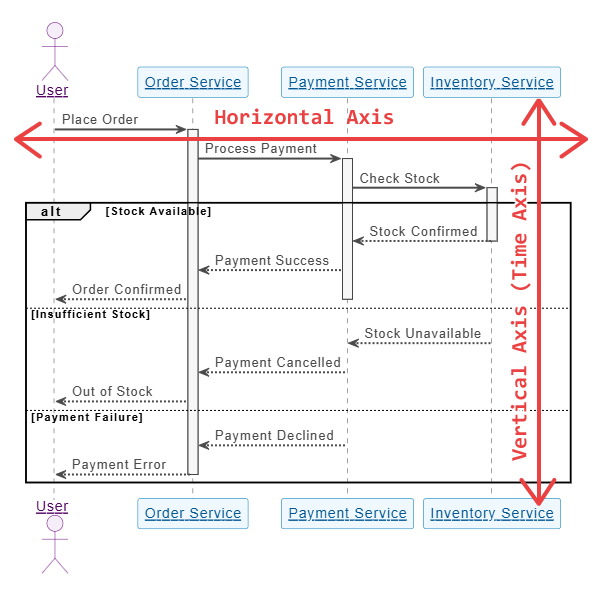
The purpose is to answer the question: “In this specific scenario (use case), in what order do these objects exchange information to achieve the desired result?”
Fundamental Elements of a Sequence Diagram
To model a sequence, you need three core elements: Lifelines, Messages, and Activation Bars.
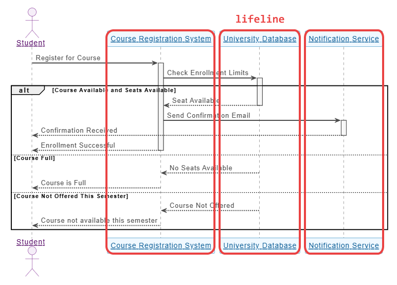
A. Lifelines (Participants)
A Lifeline represents a single participant—an object, instance, or class—in the interaction.
- Notation: A rectangular box at the top of the diagram containing the object’s name, with a vertical dashed line extending downward.
- Syntax:
ParticipantName(if the object is an instance, e.g.,user)InstanceName: ClassName(e.g.,authService: AuthenticationService)
- Purpose: The dashed line indicates the participant’s existence over time within the scope of the sequence.
B. Messages (Interaction)
Messages are the horizontal arrows drawn between lifelines. They represent the communication between objects, such as method calls, signals, or API requests.
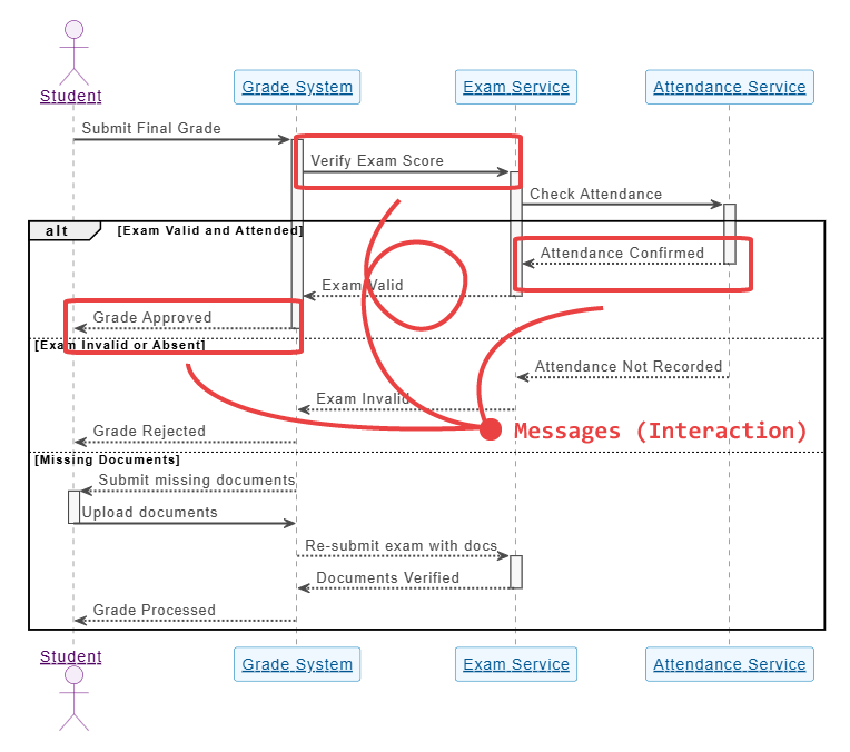
Types of Messages:
| Message Type | Notation | Description |
|---|---|---|
| Synchronous Call | Solid line with a filled arrowhead | The sender waits for a response before continuing. This initiates an Activation Bar on the recipient’s lifeline. |
| Reply/Return | Dashed line with an open arrowhead | The response to a synchronous call, indicating the return of control to the sender. This typically closes the Activation Bar. |
| Asynchronous Message | Solid line with an open arrowhead | The sender does not wait for a response and continues its own execution immediately. Common in event-driven architectures. |
| Self-Call | Arrow that loops back onto the same lifeline | An object calling one of its own methods. |
| Found Message | Arrow starting from an endpoint and hitting a lifeline | The message’s sender is unknown or outside the scope of the diagram (e.g., an external trigger). |
C. Activation Bars (Execution Specification)
The Activation Bar (also called a focus of control) is a thin vertical rectangle drawn on top of a lifeline.
- Notation: A solid vertical rectangle on a lifeline.
- Purpose: It denotes the period during which an object is actively performing an operation (i.e., its method is running) or waiting for a synchronous return. It starts when a synchronous message is received and ends when the reply message is sent.
Modeling Logic and Control Flow
To model complex business logic, you use fragments (or boxes) to surround sections of the diagram.
A. Combined Fragments
Combined Fragments allow you to model conditional logic, repetition, and optional steps. The most common fragments include:
- Alternative (alt): Used for if-else logic. The fragment is divided by a dashed line, and each section includes a condition (a “guard”) in square brackets. Only one path can be taken.
- Example:
[if user credentials are valid]and[else / invalid credentials].
- Example:
- Option (opt): Used for an if statement. The interaction inside the fragment is optional and only executes if the condition (guard) is true.
- Example:
[if user has items in cart].
- Example:
- Loop (loop): Used for repetition. The guard specifies the condition for iteration (e.g.,
[for each item]or[while (retries < 3)]). - Reference (ref): Used to modularize the diagram by referencing an interaction sequence defined in another, separate sequence diagram. This prevents diagrams from becoming too cluttered.
- Critical (crit): Used to indicate a section that must not be interrupted, often used to model concurrent processes.
Step-by-Step Modeling Example
Let’s model a simplified User Checkout Process using the core elements:
| Step | Action | Message Type |
|---|---|---|
| 1. | User clicks “Checkout.” | Synchronous Call |
| 2. | Frontend validates the cart. | Self-Call (on Frontend) |
| 3. | Frontend requests payment processing. | Synchronous Call |
| 4. | Payment Gateway checks funds. | Synchronous Call |
| 5. | Payment Gateway returns “Success.” | Return Message |
| 6. | Frontend sends an asynchronous message to the Inventory service to reduce stock. | Asynchronous Message |
| 7. | Frontend sends a synchronous message to the Order Service to finalize the order. | Synchronous Call |
| 8. | Order Service returns “Order ID.” | Return Message |
| 9. | Frontend displays a confirmation page. | Return Message (to User) |
Modeling Logic (Alternative Fragment)
To handle failure, we use an Alternative fragment:
- Place the Payment Gateway Check (Step 4 & 5) inside an
altfragment. - The first section is guarded by
[Success]. This section contains Steps 6, 7, 8, and 9. - The second section, divided by the dashed line, is guarded by
[Failure]. This section contains a new synchronous message:paymentService -> frontend: return "Payment Failed"and the Frontend displays an error page.
Summary of Sequence Diagram Best Practices
- Keep it Focused: A single Sequence Diagram should typically model a single use case or a single, atomic operation (e.g., “Login,” “Add Item to Cart”). Use Reference Fragments for sub-processes.
- Label Messages Clearly: Use verb phrases for messages, reflecting method names or API endpoints (e.g.,
processPayment(amount, token)). - Identify Participants Correctly: Distinguish between the Actor (external entity) and the Object (internal system component or instance).
- Time Flows Down: Ensure messages are consistently ordered from top to bottom.
- Use Fragments for Control: Avoid drawing complex decision nodes or loops within the message flow itself; use
alt,opt, andloopfragments.
To get more details on UML and its AI-driven visualization methods, visit our UML resource hub.
This post is also available in Deutsch, Español, فارسی, Français, English, Bahasa Indonesia, 日本語, Polski, Portuguese, Ру́сский, Việt Nam, 简体中文 and 繁體中文.