


Use cases show what your system should do. Activity diagrams allow you to specify how your system will accomplish its goals.
Activity diagrams are one of the most accessible UML diagrams since they use symbols similar to the widely-known flowchart notation; therefore, they are useful for describing processes to a broad audience. In fact, activity diagrams have their roots in flowcharts, as well as UML state diagrams, data flow diagrams, and Petri Nets.
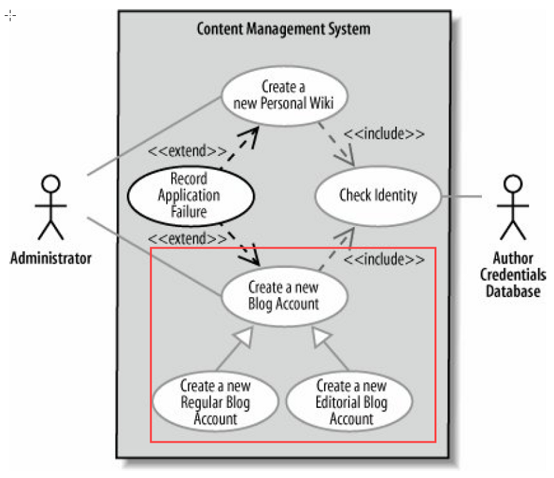
Activity diagrams show high-level actions chained together to represent a process occurring in your system. Activity diagrams are particularly good at modeling business processes.
A business process is a set of coordinated tasks that achieve a business goal, such as shipping customers’ orders. Some business process management (BPM) tools allow you to define business processes using activity diagrams, or a similar graphical notation (like BPMN), and then execute them. This allows you to define and execute, for example, a payment approval process where one of the steps invokes a credit card approval web service using an easy graphical notation such as activity diagrams.
For example, you can use an activity diagram to model the steps involved with creating a blog account.
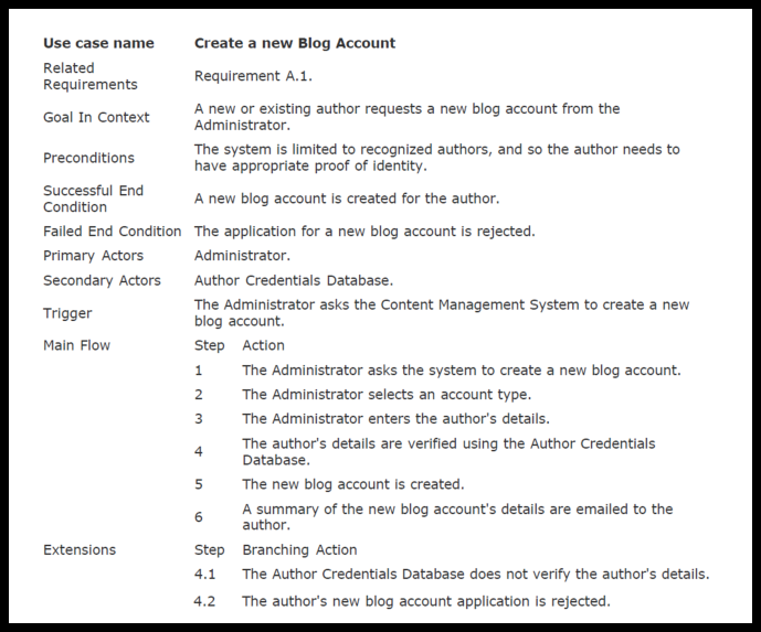
Let’s look at the basic elements of activity diagrams by modeling the steps in the blog account creation use case. The following Table contains the Create a new Blog Account use case description. The Main Flow and Extension sections describe steps in the blog account creation process.
Now let’s elaborating the use case (from requirement — what to the high level logic workflow — How) with an activity diagram :

In between the initial node and the activity final node are actions , which are drawn as rounded rectangles. Actions are the important steps that take place in the overall activity, e.g., Select Account Type, Enter Author’s Details, and so on. An action could be a behavior performed, a computation, or any key step in the process.
The flow of the activity is shown using arrowed lines called edges or paths. The arrowhead on an activity edge shows the direction of flow from one action to the next. A line going into a node is called an incoming edge, and a line exiting a node is called an outgoing edge. Edges string the actions together to determine the overall activity flow: first the initial node becomes active, then the first diamond-shaped node is called a decision, analogous to an if-else statement in code.
Notice that there are two outgoing edges from the decision in Figure above, each labeled with Boolean conditions. Only one edge is followed out of the decision node depending on whether the author is authorized. The second diamond-shaped node is called a merge. A merge node combines the edges starting from a decision node, marking the end of the conditional behavior.
Other Related Articles
- What is Use Case Diagram?
- User Story vs Use Case for Agile Software Development
- What is Use Case Specification?
This post is also available in Deutsch, Español, فارسی, Français, English, Bahasa Indonesia, 日本語, Polski, Portuguese, Ру́сский, Việt Nam, 简体中文 and 繁體中文.