


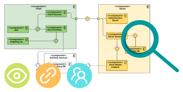
In modern software architecture, especially with the rise of microservices and complex, distributed applications, the ability to break a system into logical, manageable, and replaceable units is paramount. The UML Component Diagram is the dedicated tool for this task. It provides a high-level, structural view of a system, illustrating how the entire application is organized as a set of interconnected, replaceable, and well-defined modules called components.
This diagram moves away from the internal details of classes (seen in Class Diagrams) and focuses on the big picture: the architectural organization and the dependencies between the significant building blocks of the system.
What is a Component?
In UML, a component is a modular, deployable, and replaceable part of a system that encapsulates its contents and manifests its interfaces. Essentially, a component is a black box that offers certain services and requires others.
Key characteristics of a UML component:
-
Modular: It is a logical, self-contained unit.
-
Deployable: It can be independently deployed to an execution environment.
-
Replaceable: You can swap out one component implementation for another, provided the interfaces remain the same.
-
Encapsulated: Its internal implementation details are hidden from the outside world.
Components are typically represented as a rectangle with a specialized icon—often a small rectangle with two smaller rectangles protruding from its side—or by using the $\ll component \gg$ stereotype.
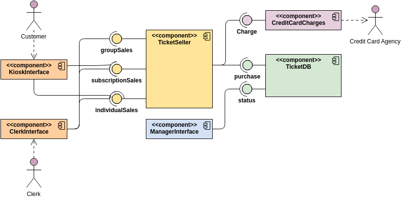
Visualizing Interfaces: The Plugs and Sockets
The power of the Component Diagram lies in how it visualizes the contracts between these modules using interfaces. Interfaces define the operations or services that a component provides or requires.
-
Provided Interfaces (The Lollipop/Ball Notation):
-
This interface represents the services or functionality the component offers to the rest of the system.
-
It is drawn as a solid line connecting a circle (the lollipop) to the component.
-
Example: A
BillingServicecomponent might provide an interface calledIProcessPayment.
-
-
Required Interfaces (The Socket/Half-Circle Notation):
-
This interface represents the services or functionality the component needs from other components to perform its job.
-
It is drawn as a solid line connecting a half-circle (the socket) to the component.
-
Example: A
OrderProcessorcomponent might require an interface calledIInventoryCheck.
-
When a component’s required interface connects directly to another component’s provided interface (the socket plugs into the lollipop), it signifies a successful dependency resolution and shows the flow of interaction.
Why Use a Component Diagram?
Component Diagrams are essential for several architectural and project management tasks:
-
Architectural Clarity: They offer a high-level view of the system structure, making it easy to understand the major functional units and their relationships without getting lost in code details.
-
Modularity and Reuse: They enforce the concept of modular design by focusing on clean interfaces, encouraging the creation of reusable components that can be shared across multiple systems.
-
Dependency Management: By explicitly showing interfaces and connections, the diagrams clarify which components depend on others. This is critical for managing build order, deployment sequencing, and minimizing ripple effects during changes.
-
System Deployment Planning: They act as an input for Deployment Diagrams by identifying the specific modular units that need to be packaged and deployed onto physical nodes.
-
Team Allocation: Component boundaries often align with team boundaries (especially in a microservices environment), helping to define clear responsibilities and ownership.
Key Elements of the Component Diagram
| Element | Notation | Description |
| Component | Rectangle with << component >> or special icon | A deployable, replaceable, modular part of the system. |
| Provided Interface | Circle (“Lollipop”) connected by a solid line | Functionality or services the component offers to others. |
| Required Interface | Half-circle (“Socket”) connected by a solid line | Functionality or services the component needs from others. |
| Port | Small square on the boundary of a component | A point of interaction between a component and its environment or between internal parts. |
| Dependency | Dashed arrow from the requiring component to the providing component | A general relationship indicating one element needs another. (Often implied by the lollipop/socket connection.) |
The UML Component Diagram provides the necessary abstraction layer between the detailed design of classes and the physical deployment of the system, making it an indispensable tool for designing resilient and modular software architectures.
Discover more about UML and the AI techniques used to visualize it in our UML resource hub.
This post is also available in Deutsch, Español, فارسی, Français, English, Bahasa Indonesia, 日本語, Polski, Portuguese, Ру́сский, Việt Nam, 简体中文 and 繁體中文.