


Unified Modeling Language (UML) is a graphical language used for visual modeling in software engineering. UML provides a standardized notation that helps software developers to design and communicate software systems effectively. UML is widely used in software development because it allows developers to capture the system’s requirements, design, and functionality in a visual format that is easy to understand.

UML was initially developed in the mid-1990s by Grady Booch, James Rumbaugh, and Ivar Jacobson, and it has since been adopted as an industry standard by the Object Management Group (OMG). The OMG continues to maintain and update the UML specification, which has undergone several revisions over the years.
Learning UML is essential for software developers, system analysts, and other stakeholders involved in software development. UML provides a common language and a standard notation for modeling software systems, which facilitates communication and collaboration between team members. By learning UML, developers can create clear and concise models of software systems that can be easily shared and understood.
The 14 Types of UML diagrams
UML consists of 14 types of diagrams that can be used to model different aspects of a software system.
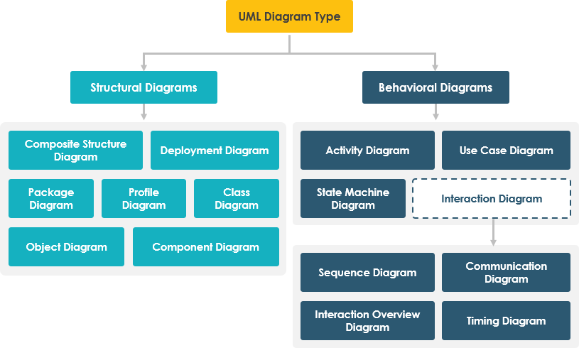
Here’s a brief introduction to each of the 14 UML diagram types:
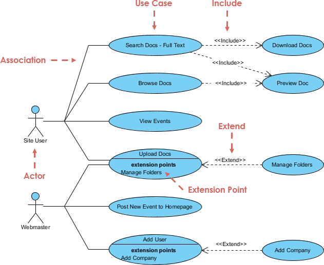
- Use Case Diagrams: These diagrams depict the interactions between the system and the actors or users. They help to identify the use cases or functional requirements of the system and show how the system will be used by the end-users.
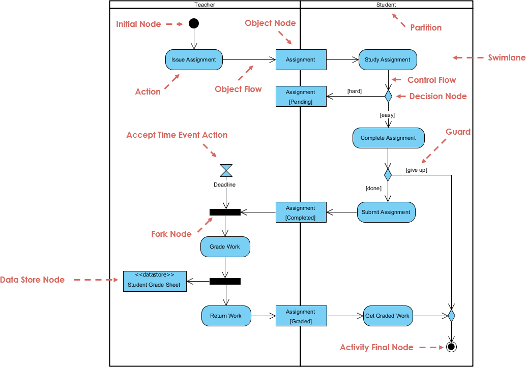
- Activity Diagrams: Activity diagrams depict the flow of control or the sequence of activities in a system. They help to describe the workflow of a system and how different activities or tasks are related.
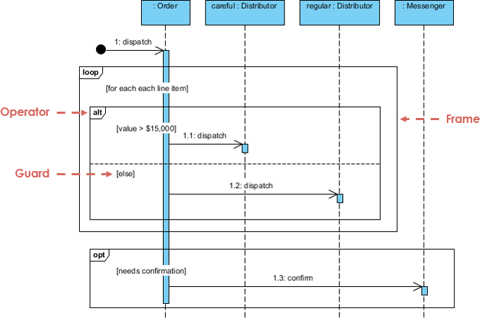
- Sequence Diagrams: Sequence diagrams depict the interactions between objects or components in a system. They help to describe the messages or events exchanged between objects and how they interact with each other.
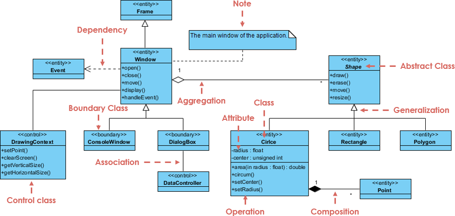
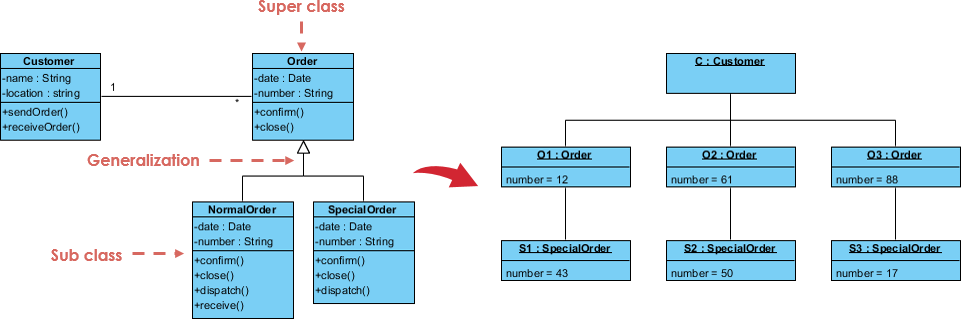
- Class Diagrams: Class diagrams depict the classes, objects, and their relationships in a system. They help to describe the structure of a system and how different objects or components are related to each other.
- Object Diagrams: Object diagrams depict the instances of objects or components in a system. They help to describe the current state of a system and how different objects or components are related to each other.
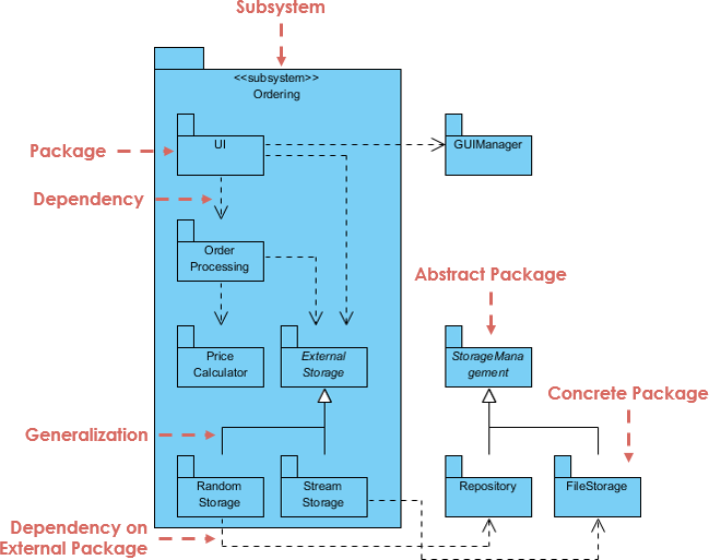
- Package Diagrams: Package diagrams depict the packages and their relationships in a system. They help to organize the different components or modules in a system and show how they are related.
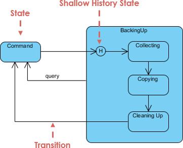
- State Machine Diagrams: State machine diagrams depict the states and state transitions of objects or components in a system. They help to describe the behavior of a system and how it changes based on different events or conditions.
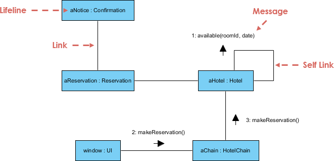
- Communication Diagrams: or Collaboration diagrams depict the interactions between objects or components in a system. They help to describe how different objects or components work together to achieve a specific task or goal.
- Component Diagrams: Component diagrams depict the components or modules in a system and their relationships. They help to describe the physical structure of a system and how different components or modules are related to each other.
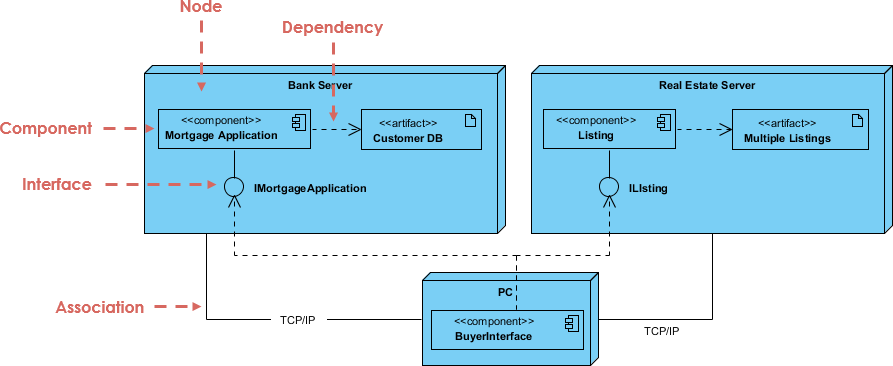
- Deployment Diagrams: Deployment diagrams depict the physical deployment of components or modules in a system. They help to describe how different components or modules are deployed on hardware or software platforms.
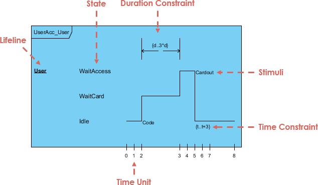
- Timing Diagrams: Timing diagrams depict the timing constraints or temporal behaviors of objects or components in a system. They help to describe how different events or actions are related in time.
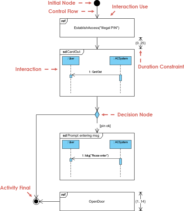
- Interaction Overview Diagrams: Interaction overview diagrams depict the interactions and control flow between different interaction fragments in a system. They help to describe the flow of control between different interaction fragments or sub-activities in a system.
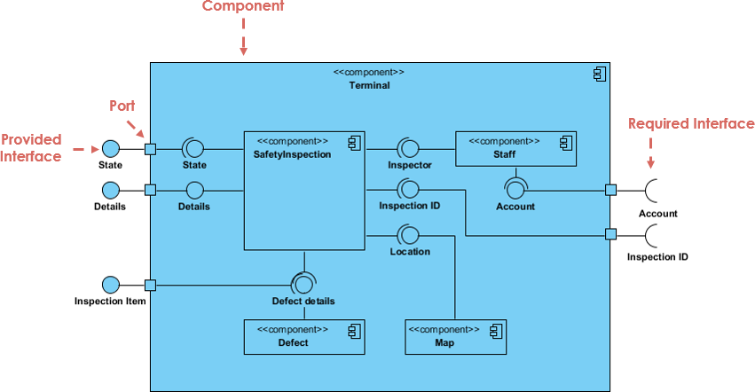
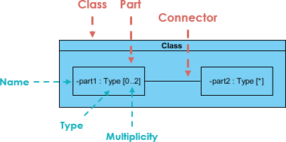
- Composite Structure Diagrams: Composite structure diagrams depict the internal structure of a classifier or composite structure in a system. They help to describe the internal components or sub-components of a classifier or composite structure.
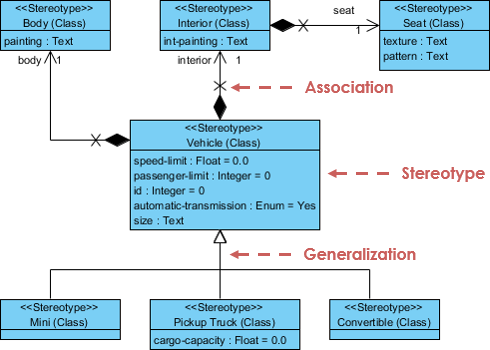
- Profile Diagrams: Profile diagrams depict the stereotypes and tagged values used to extend or specialize the UML metamodel. They help to describe the customizations or extensions made to the UML language to meet the specific needs of a domain or application.
A UML tool is necessary to create and manage UML diagrams efficiently. A UML tool provides a user-friendly interface to create, edit, and share UML diagrams. It also provides features such as validation, code generation, and reverse engineering, which make the modeling process more efficient.
The Best UML tool
Visual Paradigm is a popular UML tool used by many software development teams worldwide. It provides both free and commercial plans that suit different needs and budgets. Visual Paradigm offers a comprehensive set of features that make it easy to create and manage UML diagrams. It also supports the latest UML standards and provides features such as code generation, reverse engineering, and version control.
The advantages of Visual Paradigm UML tool include:
- Comprehensive set of features
- User-friendly interface
- Supports the latest UML standards
- Offers both free and commercial plans
- Provides code generation and reverse engineering features
- Supports version control and team collaboration
- Offers a wide range of customization options
In summary, UML is a graphical language used for visual modeling in software engineering. It provides a standardized notation that helps software developers to design and communicate software systems effectively. UML consists of 14 types of diagrams that can be used to model different aspects of a software system. Visual Paradigm is a popular UML tool that provides a comprehensive set of features and supports the latest UML standards. Learning UML and using a UML tool like Visual Paradigm can significantly improve the efficiency and effectiveness of software development.
References
- What is UML Collaboration Diagram?
- UML Association vs Aggregation vs Composition
- UML Class Diagram Tutorial
- How to Model Constraints in UML?
- State Machine Diagram vs Activity Diagram
- How to Identify Actors?
- Types of Actor in Use Case Model
- What is Model-View and Control?
- How to Model MVC Framework with UML Sequence Diagram?
- UML – Behavioral Diagram vs Structural Diagram
- What is UML Extensibility Mechanism?
- UML Practical Guide – All you need to know about UML modeling
- UML Modeling, Software Process and Tool
- UML – Modeling Software Architecture with Packages
- All You Need to Know about State Diagrams
This post is also available in Deutsch, Español, فارسی, Français, English, Bahasa Indonesia, 日本語, Polski, Portuguese, Ру́сский, Việt Nam, 简体中文 and 繁體中文.