
Your Learning Path: From Novice to Expert
Welcome to your comprehensive guide on UML Object Diagrams. This journey-based guide is designed specifically for IT developers who want to master the art of visualizing system snapshots and runtime structures.
Phase 1: Foundation – Understanding the Basics
What is an Object Diagram?
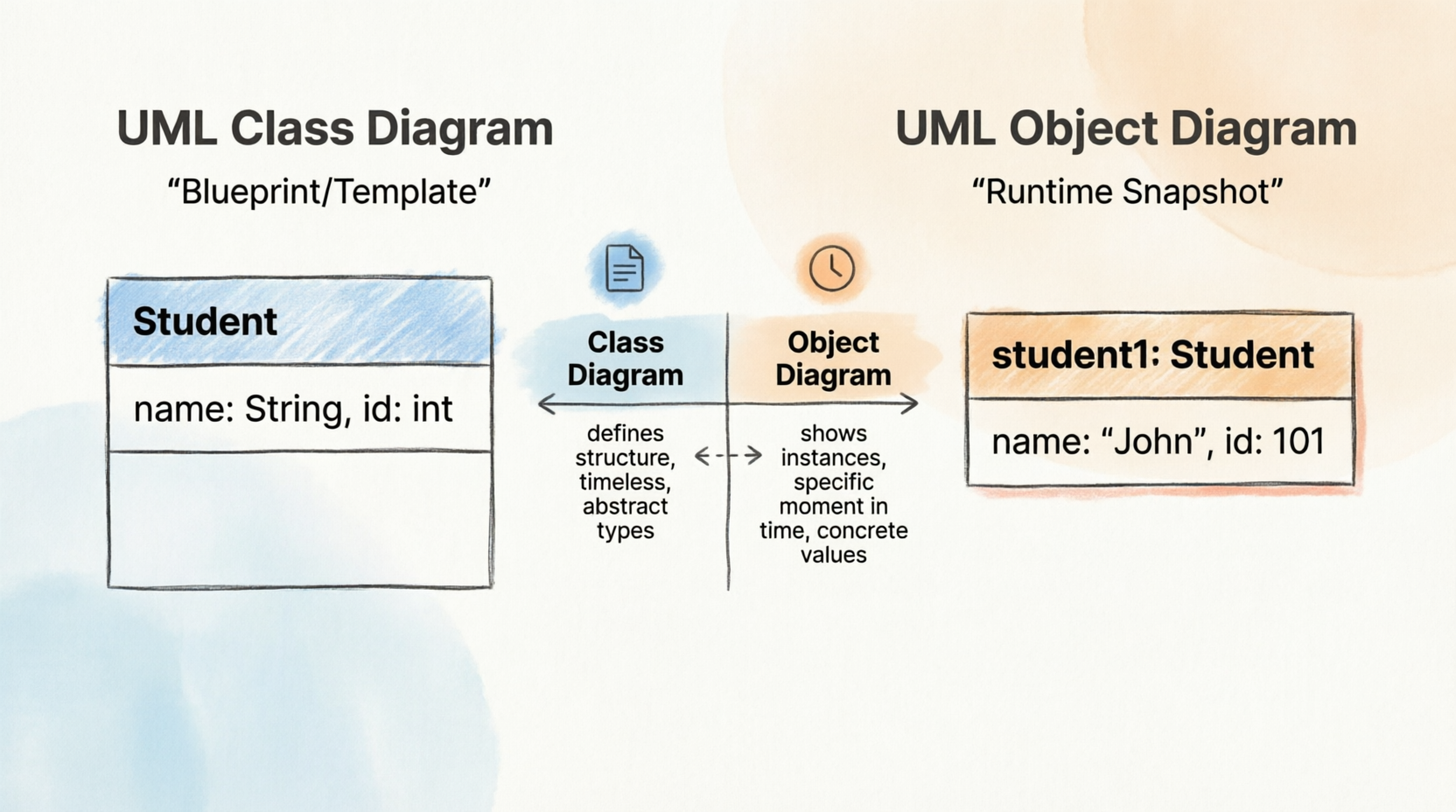
An Object Diagram is a specialized type of diagram in the Unified Modeling Language (UML) that captures a specific “snapshot” of a system at a particular moment during runtime.
While a Class Diagram acts as the blueprint or template defining the structure and rules of a system, an Object Diagram shows the actual instances (objects) that exist within that system right now. It depicts:
-
The specific objects created from classes.
-
Their current state (attribute values).
-
The active relationships (links) between them.
The Cookie Cutter Analogy: If a Class is a cookie cutter, an Object is the actual cookie. An object diagram doesn’t show you the shape of the cutter; it shows you the cookies currently on the plate, complete with their specific shapes and decorations.
Phase 2: Purpose – Why Object Diagrams Matter
Real-World Applications for Developers
Object diagrams are used more selectively than other diagram types. They’re not meant to describe the entire system design but rather specific scenarios. Their primary purposes include:
✅ Verification: During the analysis phase, you might create a class diagram to define structure. You can then generate object diagrams as “test cases” to verify if the class diagram accurately represents real-world data structures.
✅ Discovery: Before finalizing a class diagram, you can sketch an object diagram to discover facts about specific model elements, their links, or to illustrate concrete examples of the classifiers required.
When Should You Use Object Diagrams?
Object diagrams illustrate the relationship between instantiated classes and their defined classes, as well as the relationships between these objects within the system. They are particularly useful when:
-
Explaining smaller, complex portions of a system where the overall class diagram is too cluttered
-
Modeling recursive relationships (where an object relates to another object of the same type)
-
Debugging runtime issues by visualizing actual object states
-
Documenting specific scenarios for stakeholder communication
Understanding the Concept
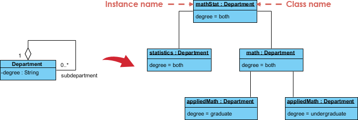
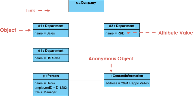
The best way to understand an object diagram is to see it derived from its corresponding class diagram. For example, consider an Order Management System. A small class diagram might show that a university Department can contain many other Departments. The object diagram below instantiates this class diagram, replacing abstract definitions with a concrete example.
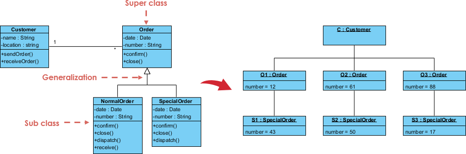
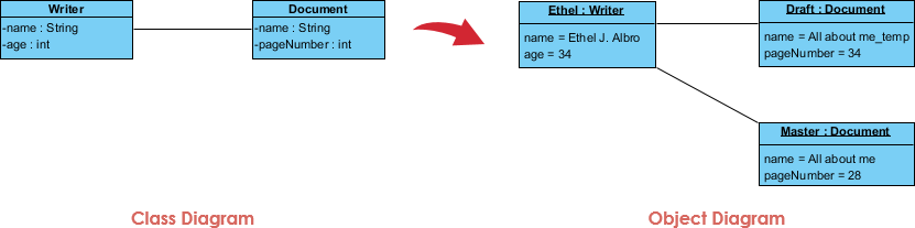
Class to Object Diagram Example – Order System
The following image demonstrates how a general class structure transforms into specific object instances with assigned values.
Phase 3: Syntax – Mastering the Notation
Basic Symbols and Notations
Object diagrams use notation very similar to class diagrams but with specific distinctions regarding values and instantiation.
| Symbol Type | Description | Visual Representation |
|---|---|---|
| Object Names | Every object is symbolized by a rectangle containing the object’s name and its class name (underlined), separated by a colon (e.g., objectName : ClassName). |
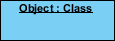 |
| Object Attributes | Similar to classes, attributes are listed in a separate compartment. However, unlike class diagrams where attributes define types, object diagram attributes must have specific values assigned to them. | 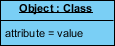 |
| Links | Links are instances of associations. They are drawn using the same line styles used in class diagrams to connect objects. | 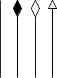 |
Phase 4: Comparison – Class vs. Object Diagrams
Understanding the distinction between these two structural diagrams is crucial for effective modeling.
| Feature | Class Diagram | Object Diagram |
|---|---|---|
| Scope | Shows actual classifiers (types) and their relationships in a system. | Shows specific instances of those classifiers and the links between them at a single point in time. |
| Nature | Represents the potential behavior and structure over time. | Represents a static view of a communication diagram or a snapshot of runtime behavior. |
| Instantiation | Defines the rules for creating objects. | Created by instantifying the classifiers found in class, deployment, component, and use-case diagrams. |
| Time | Timeless (defines the schema). | Temporal (a snapshot at a specific moment). |
Phase 5: Modern Approach – AI-Powered Diagramming
Visualize System Snapshots with AI
Object diagrams capture a specific moment in runtime, showing how classes are instantiated and linked. Visual Paradigm’s AI ecosystem helps you instantly generate these “snapshots” from class descriptions, ensuring your data structures and object states are accurately modeled.
AI-Enabled Platforms
-
VP Desktop: Generate object instances and links directly within your professional UML models using built-in AI.
-
OpenDocs: Create collaborative Specification Documents that include AI-generated object diagrams.
-
AI Chatbot: Describe a runtime scenario to the AI Chat and watch it instantiate your classes into a diagram.
Smart Runtime Modeling
🏗️ Instant Instantiation: Automatically generate an object diagram from an input problem description.
📊 High Quality: AI helps you identify objects and slots with its insights.
For more details, check out the AI Object Diagram Guide or browse All AI Tools.
Phase 6: Practice – Real-World Examples
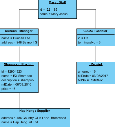
Example I: Company Structure
This example demonstrates how hierarchical organizational structures can be visualized through object instances.
Example II: Point of Sale (POS)
A practical application showing objects involved in a transaction process.
Example III: Writer
Illustrates the state of a document editing system at a specific moment.
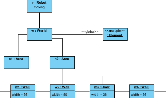
Example IV: Robot Moving Behavior
This complex example exposes the internal state and links of a robot interacting with its environment.
-
Robot
r): An instance of theRobotclass, currently in the “moving” state. -
World
w): An instance ofWorld, representing the robot’s world model. -
Elements: Multiple instances of
Elementrepresenting entities identified by the robot but not yet assigned. -
Area
a2): Linked tow, this area contains threeWallobjects and oneDoorobject. Each wall has a specific width attribute and links to neighboring walls.
This diagram suggests the robot has recognized an enclosed area with walls on three sides and a door on the fourth.
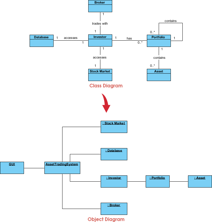
Example V: Deriving an Object Structure Similar to Communication Diagram
Besides showing state, object diagrams can represent interactions between classes at runtime. The result often resembles a communication diagram. Below is an example of a stock trading scenario.
Phase 7: Methodology – Step-by-Step Modeling Process
Steps for Modeling Object Structures
A communication diagram without messages is also known as an object diagram. To ensure consistency, an object diagram must be a valid instantiation of a static class diagram. Objects must belong to classes, and links between objects must be instances of associations between those classes.
To develop an object diagram, follow these steps:
-
Identify the Mechanism: Determine the function or behavior of the part of the system you are modeling, resulting from the interaction of a society of classes, interfaces, and other elements.
-
Identify Participants: For each mechanism, list the classes, interfaces, and other elements that participate in the collaboration, along with their relationships.
-
Freeze the Scenario: Consider one specific scenario that walks through this mechanism. Freeze this scenario at a specific moment in time.
-
Render Objects: Render each object participating in the mechanism at that frozen moment.
-
Expose State: Display the state and attribute values of each object necessary to understand the scenario.
-
Expose Links: Draw the links among these objects, ensuring they represent instances of the associations defined in the class diagram.
💡 Pro Tips & Tricks for IT Developers
Best Practices
-
Start Small: Begin with simple scenarios before tackling complex system states
-
Use Meaningful Names: Object names should reflect their real-world counterparts
-
Show Only Relevant Attributes: Don’t clutter diagrams with unnecessary attribute values
-
Validate Against Class Diagrams: Always ensure your object diagram is a valid instantiation
-
Leverage AI Tools: Use AI-powered diagramming to speed up the creation process
-
Document Assumptions: Note the specific moment in time your snapshot represents
-
Focus on Relationships: Links between objects are as important as the objects themselves
Common Pitfalls to Avoid
-
❌ Creating object diagrams that don’t match your class diagram structure
-
❌ Forgetting to assign specific values to attributes
-
❌ Overcomplicating diagrams with too many objects
-
❌ Not specifying the temporal context of your snapshot
-
❌ Ignoring multiplicity constraints from class diagrams
Quick Reference Checklist
-
Objects have underlined names with class identifiers
-
All attributes have concrete values (not types)
-
Links correspond to associations in class diagram
-
Multiplicity constraints are respected
-
The scenario represents a valid system state
-
Diagram is labeled with timestamp/context
🚀 Getting Started Now
You’ve learned what an Object Diagram is and how to draw one. It’s time to put your knowledge into practice. Get Visual Paradigm Community Edition, a free UML software, and create your own Object Diagram with the free Object Diagram tool. It’s easy-to-use and intuitive.
📚 Reference List
AI-Powered Object Diagrams: A Guide to AI-Powered Structural Visualization: This guide explores how artificial intelligence enhances structural visualization through object diagrams within the Visual Paradigm environment.
AI-Powered UML Diagramming Using Visual Paradigm: This article examines how generative AI streamlines the creation of various UML diagrams, including object diagrams, to support smarter system design.
Mastering UML Diagram Generation with Visual Paradigm AI: A comprehensive resource explaining how to create precise UML models by leveraging AI-driven automation for faster project delivery.
Visual Paradigm AI Diagram Generator: A Comprehensive Guide: This article details how to use AI-powered diagram generation to convert textual ideas into structured visual designs.
Visual Paradigm AI Chatbot: Turn Your Ideas into Diagrams Instantly: This resource highlights a chatbot that allows users to generate diagrams using natural language, making visual modeling more accessible to teams.
How AI Chatbot Can Help You Learn UML Faster: This blog post discusses how students and professionals can practice UML interactively and receive instant feedback through AI assistants.
Mastering UML Object Diagrams: A Comprehensive Guide with Visual Paradigm: A technical guide providing an overview of creating and understanding object diagrams, depicting class instances and their relationships.
How to Turn Requirements into Diagrams with an AI Chatbot: This article focuses on bridging the gap between textual requirements and visual models like object diagrams using conversational AI.
Mastering Automated Modeling: A Guide to New AI Diagram Types: A guide on leveraging new AI-powered diagramming features to automate complex modeling tasks and maintain standards compliance.
Visual Paradigm’s AI-Powered Ecosystem: Smarter Visual Modeling: An overview of how integrated AI platforms support the entire modeling lifecycle, from conversational ideation to enterprise-grade delivery.
🔗 Related Resources
What is Unified Modeling Language?: An introduction to UML, the standard language for specifying, constructing, documenting, and visualizing systems.
Professional UML diagram tool: A comprehensive guide to the features available in professional UML modeling software.
Your Journey Continues
You’ve now completed your foundational journey through UML Object Diagrams. Remember:
-
Practice regularly with real-world scenarios
-
Leverage AI tools to accelerate your workflow
-
Validate your diagrams against class structures
-
Share and collaborate with your team
-
Keep learning as UML and modeling tools evolve
Happy modeling! 🎯