
Introduction: My UML Learning Adventure
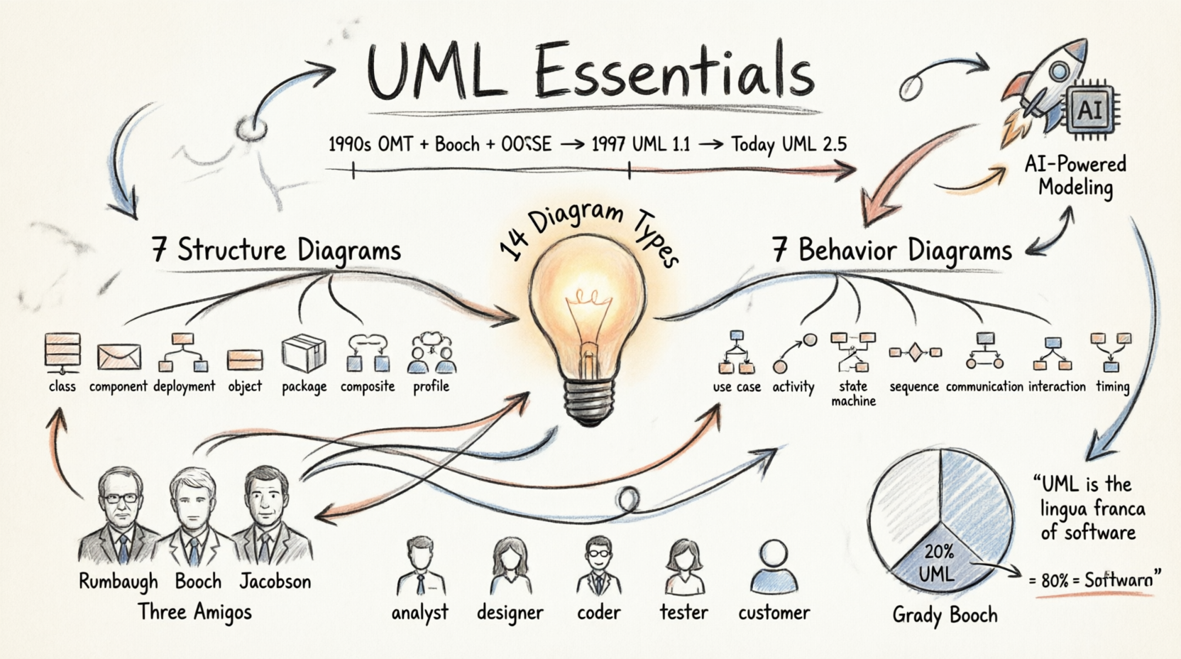
When I first encountered Unified Modeling Language (UML), I’ll be honest—it felt overwhelming. With 14 different diagram types and over 700 pages of specifications, I wondered if I’d ever make sense of it all. But here’s what I discovered on my journey: you don’t need to master everything at once.
Through trial, error, and lots of practice, I learned that UML is less about memorizing every notation and more about choosing the right visual language for your specific needs. Whether you’re documenting a complex enterprise system or sketching out a simple application architecture, UML offers tools that can transform abstract ideas into clear, communicable designs.
In this guide, I’m sharing what I’ve learned—the good, the challenging, and the surprisingly useful—so you can navigate your own UML learning path with confidence. Let’s dive in!
Understanding UML: What I Wish I’d Known Earlier
The Reality Check: UML is Huge, But You Don’t Need It All
Early in my journey, I made the mistake of trying to learn every single UML diagram type simultaneously. Big mistake! Here’s what changed my perspective:
Grady Booch, one of UML’s creators, once said: “For 80% of all software, only 20% of UML is needed.”
This was liberating. I realized I could focus on the essentials first:
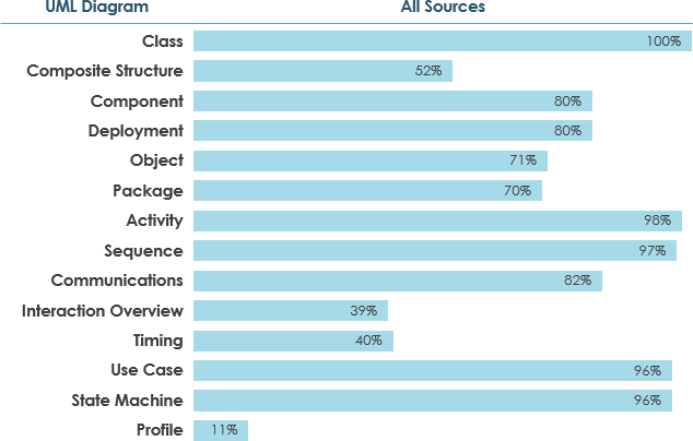
What the community uses most (based on surveys):
-
Widely used (≥60% adoption): Class Diagrams, Use Case Diagrams, Sequence Diagrams, Activity Diagrams
-
Moderately used: Component Diagrams, Deployment Diagrams, State Machine Diagrams
-
Specialized scenarios: The remaining diagrams serve specific architectural or analysis needs
My Recommended Learning Path
Based on my experience and survey data, here’s how I suggest approaching UML:
-
Start with the Big Three: Use Case, Class, and Sequence Diagrams
-
Add Process Flow: Activity Diagrams
-
Expand to Architecture: Component and Deployment Diagrams
-
Master State Behavior: State Machine Diagrams
-
Explore Advanced Types: As needed for your projects
The Origins: How UML Came to Be
Understanding UML’s history helped me appreciate why it’s structured the way it is. Here’s the fascinating story:
The “Three Amigos” Unite
In the early 1990s, three brilliant minds were working on separate object-oriented methods:
-
James Rumbaugh – Created OMT (Object Modeling Technique) in 1991
-
Best for: Analysis and data-intensive information systems
-
-
Grady Booch – Developed the Booch Method in 1994
-
Best for: Design and implementation
-
Fun fact: His notation used lots of cloud shapes (not very tidy!)
-
-
Ivar Jacobson – Created OOSE (Object-Oriented Software Engineering) in 1992
-
Key contribution: Use Cases – revolutionary for understanding system behavior
-
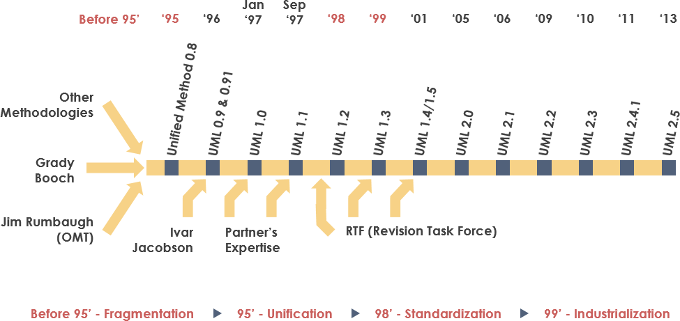
The game-changer: In 1994, Rumbaugh left General Electric to join Booch at Rational Corp. Their goal? Merge their methods into a “Unified Method.” By 1995, Jacobson joined them, bringing Use Cases into the mix. The “Three Amigos” were born!
Standardization Journey
-
1996: OMG (Object Management Group) issued the first Request for Proposal (RFP)
-
1997: UML 1.0 submitted to OMG
-
Late 1997: UML 1.1 adopted after incorporating feedback from IBM, ObjecTime, and others
-
Evolution: Progressed through versions 1.5, 2.0, 2.1, and now UML 2.5
Why I Use UML: Real-World Benefits
After working with UML on multiple projects, here are the tangible benefits I’ve experienced:
1. Communication Across Teams
UML gave me a common language to discuss complex systems with:
-
Analysts – who need to understand requirements
-
Developers – who implement the design
-
Testers – who verify functionality
-
Stakeholders – who need high-level overviews
-
Technical writers – who document the system
2. Managing Complexity
As systems grew in scope, UML helped me tackle:
-
Physical distribution challenges
-
Concurrency issues
-
Security architecture
-
Load balancing strategies
-
Fault tolerance planning
3. Design Before Code
I learned to visualize architectures before writing a single line of code, saving countless hours of refactoring.
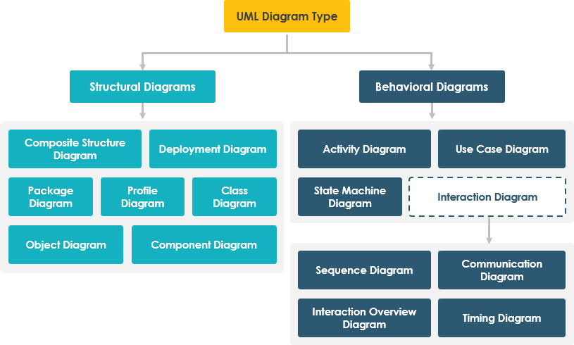
The 14 UML Diagram Types: My Hands-On Experience
UML diagrams fall into two main categories. Let me share what I’ve learned about each:
STRUCTURE DIAGRAMS (Static View)
These diagrams show the static structure of your system—what exists and how it’s organized.
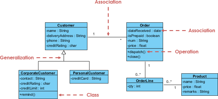
1. Class Diagram: The Backbone of OO Design
What I use it for: This is my go-to diagram for nearly every object-oriented project. It shows:
-
Classes in your system
-
Attributes and operations
-
Relationships between classes
Key relationships I model:
-
Association: “A person works for a company”
-
Inheritance: “A Manager is an Employee”
-
Aggregation: “A Department has Employees”
Class Diagram Example:
My tip: Start with a high-level view, then drill down into complex classes. Don’t try to model everything at once!
2. Component Diagram: Mapping Software Architecture
When I reach for this: When I need to show how larger components wire together to form systems.
What it reveals:
-
Software components (runtime, executable, source code)
-
Dependencies between components
-
System architecture at a glance
Component Diagram Example:
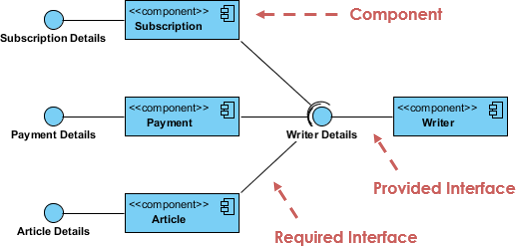
Real-world use: I used this extensively when migrating a monolithic application to microservices—it helped visualize component boundaries.
3. Deployment Diagram: Visualizing Physical Infrastructure
My deployment planning tool: This diagram models the physical aspects of your system.
What I model:
-
Hardware configurations (servers, devices)
-
Software artifacts deployed to each node
-
Network topology
-
Runtime configuration
Deployment Diagram Example:
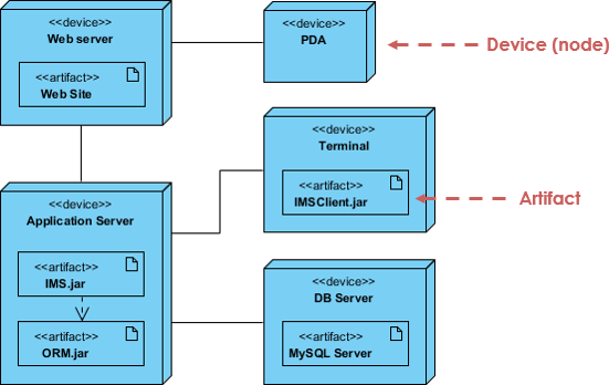
Pro tip: Use this when planning cloud deployments or distributed systems—it’s invaluable for infrastructure discussions.
4. Object Diagram: Snapshots in Time
The “aha!” moment: I initially confused Object Diagrams with Class Diagrams. Here’s the difference:
-
Class Diagram: Abstract model (the blueprint)
-
Object Diagram: Concrete instance at a specific moment (the actual building)
When I use it: To show examples of data structures or validate my class designs.
Comparing the Two:
Class Diagram Example (the template):
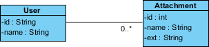
Object Diagram Example (a specific moment – Peter uploading two attachments):
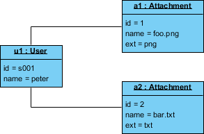
My insight: Object diagrams are limited in use but powerful for debugging and understanding specific scenarios.
5. Package Diagram: Organizing Complexity
My organizational tool: When systems grow large, I use package diagrams to:
-
Group related elements logically
-
Show dependencies between packages
-
Model multi-layered architectures
Package Diagram Example:
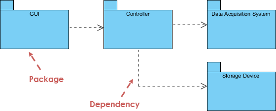
Best practice: I organize packages by feature or layer (presentation, business, data) depending on the project.
6. Composite Structure Diagram: Inside the Black Box
New in UML 2.0: This was unfamiliar to me initially, but it’s powerful for micro-level modeling.
What it shows:
-
Internal structure of classes
-
Individual parts (not whole classes)
-
Ports for interaction
-
Connectors between parts
Composite Structure Diagram Example:
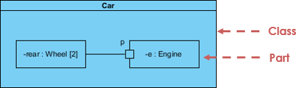
When it shines: Modeling complex collaborations within a single class or component.
7. Profile Diagram: Customizing UML
My customization toolkit: Profile diagrams let me create domain-specific extensions.
Capabilities:
-
Define custom stereotypes
-
Create tagged values
-
Establish domain-specific relationships
Profile Diagram Example:
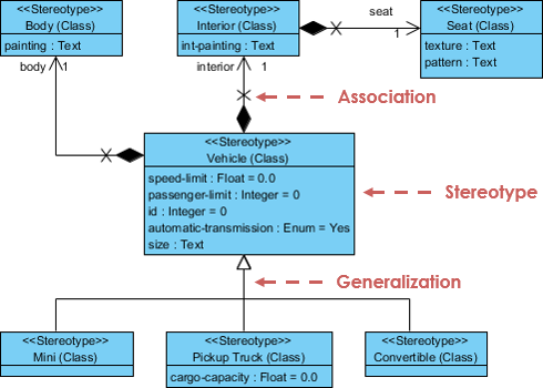
My use case: I created a profile for financial systems with stereotypes like “RegulatedEntity” and “AuditTrail.”
BEHAVIOR DIAGRAMS (Dynamic View)
These diagrams capture how your system behaves over time.
8. Use Case Diagram: The User’s Perspective
My starting point for every project: Use case diagrams model system functionality from the user’s viewpoint.
The restaurant menu analogy: Just as a menu shows you what’s available (dishes, prices, cuisine type), a use case diagram shows:
-
Actors: Who interacts with the system
-
Use Cases: What the system does
-
Relationships: How actors and use cases connect
Use Case Diagram Example:
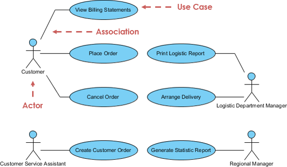
Why I love it: It’s the perfect tool for requirements gathering with non-technical stakeholders. Everyone understands a menu!
9. Activity Diagram: Mapping Workflows
My process visualization tool: Think of this as a sophisticated flowchart.
What I model:
-
Step-by-step activities
-
Decision points (branches)
-
Parallel operations (forks/joins)
-
Complex business rules
-
Workflow processes
Activity Diagram Example:
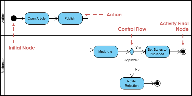
Real application: I’ve used activity diagrams to document approval workflows, data processing pipelines, and user onboarding flows.
10. State Machine Diagram: Tracking Object Lifecycles
Understanding state-based systems: This diagram shows how objects change states in response to events.
Key elements:
-
States (what the object is doing)
-
Transitions (how it moves between states)
-
Events (what triggers transitions)
State Machine Diagram Example:
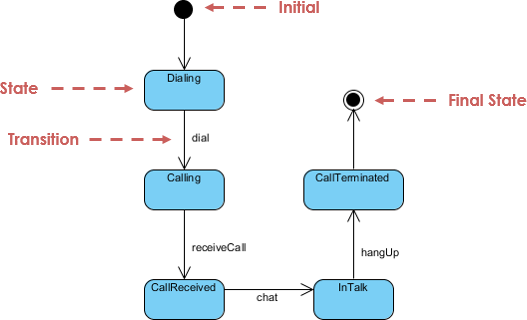
My experience: Invaluable for modeling order processing (Pending → Approved → Shipped → Delivered) or user account states.
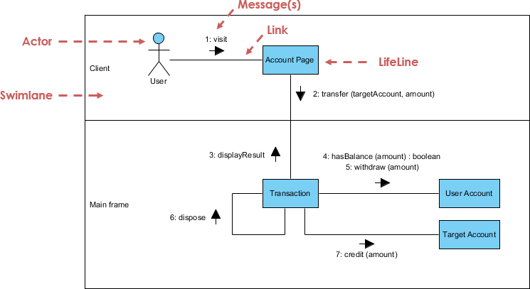
11. Sequence Diagram: Time-Based Interactions
My collaboration mapper: This shows how objects interact over time.
What it reveals:
-
Message flow between objects
-
Temporal ordering of interactions
-
Lifelines showing object existence
-
Specific use case scenarios
Sequence Diagram Example:
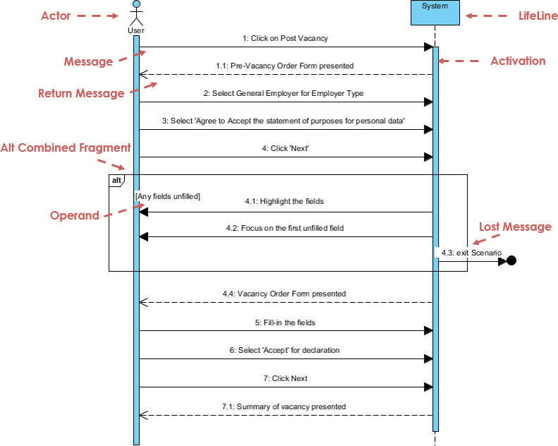
Power feature: Some tools (like Visual Paradigm) can generate sequence diagrams directly from use case descriptions—huge time saver!
12. Communication Diagram: Object Collaboration Focus
Similar to sequence, different emphasis: While sequence diagrams focus on time, communication diagrams emphasize object relationships.
Key difference:
-
Sequence Diagram: “When does this happen?”
-
Communication Diagram: “Who talks to whom?”
Communication Diagram Example:
My workflow: I often create one and let my modeling tool generate the other—they’re semantically equivalent!
13. Interaction Overview Diagram: High-Level Flow Control
The big picture of interactions: This is a variant of activity diagrams focused on interaction flow.
Unique features:
-
Nodes represent interactions (not activities)
-
Messages and lifelines are hidden
-
Links to detailed diagrams
-
High navigability between diagrams
Interaction Overview Diagram Example:
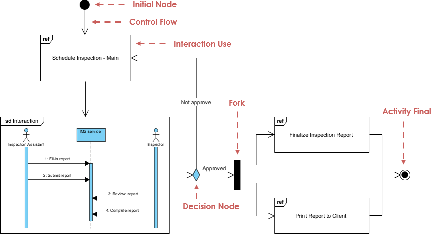
When I use it: For complex systems with multiple interacting scenarios—provides the “table of contents” for detailed interactions.
14. Timing Diagram: Precise Time Constraints
The specialist’s tool: A special form of sequence diagram with reversed axes.
Differences from sequence diagrams:
-
Time increases left to right (not top to bottom)
-
Lifelines in separate vertical compartments
-
Focus on timing constraints
Timing Diagram Example:
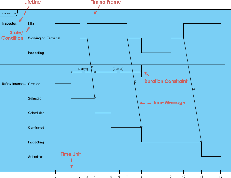
My use cases: Real-time systems, embedded systems, or anywhere precise timing matters (like traffic light controllers).
Modern UML: My Experience with AI-Powered Tools
The Game Changer: AI-Assisted Diagramming
Just when I thought I had UML figured out, AI tools entered the scene—and they’ve transformed my workflow!
Visual Paradigm’s AI ecosystem has made diagramming faster and more intuitive:

1. AI Diagram Chatbot 💬
I simply describe my system in plain English, and it drafts the appropriate UML diagram instantly. I can even ask follow-up questions to refine the logic.
👉 Try it: AI Diagram Chatbot
2. AI WebApps 🌐
Step-by-step AI-guided workflows help me create, refine, and evolve complex diagrams through an intuitive web interface.
👉 Explore: AI WebApps
3. Desktop AI Generator ⚡
I access high-speed automated diagramming directly within Visual Paradigm Desktop for professional-grade modeling.
👉 Learn more: Diagram Generator Guide
4. OpenDocs Knowledge Management 📝
I seamlessly embed AI-generated diagrams into my documentation, keeping technical knowledge and visual models perfectly synchronized.
👉 Discover: OpenDocs
The complete ecosystem: Explore AI Diagram Generation
My UML Toolkit: Essential Resources
Free UML Software Recommendation
When I started, budget was tight. Visual Paradigm Community Edition became my lifeline:
✅ Supports all 14 UML diagram types
✅ Award-winning, intuitive interface
✅ Completely free for learning
✅ International recognition
📥 Download: Visual Paradigm Community Edition
UML Glossary: Terms I Reference Constantly
Throughout my journey, I’ve built a personal glossary. Here are the terms I use most:
A-C
-
Abstract Class: A class that will never be instantiated
-
Actor: A person or object that initiates system events
-
Activity: A step or action in an Activity Diagram
-
Aggregation: “Part of” relationship (shown with hollow diamond)
-
Association: Connection between two model elements
-
Attribute: Characteristics of an object
-
Class: A category of similar objects
-
Component: A deployable unit of code
-
Concurrency: Multiple operations happening simultaneously
D-G
-
Deployment Diagram: Shows processor relationships
-
Encapsulation: Data in objects is private
-
Generalization: Inheritance relationship (hollow arrow to superclass)
-
Guard Condition: Boolean expression controlling a transition
I-M
-
Inheritance: Subclasses inherit parent class attributes
-
Interface: A contract for behavior
-
Message: A request from one object to another
-
Multiplicity: Object quantity relationships
-
Method: A function or procedure in an object
O-S
-
Object: An instance of a class
-
Package: A logical grouping of UML elements
-
Polymorphism: Same message, different method
-
State: What a system is doing at a point in time
-
Stereotype: Custom UML “dialect” modifier
T-Z
-
Transition: Change from one state to another
-
Use Case: An action the system takes in response to an actor
-
Visibility: Access levels (Public, Protected, Private)
-
Workflow: A set of activities producing a specific result
Books That Transformed My UML Understanding
These resources accelerated my learning significantly:
-
UML Distilled: A Brief Guide to the Standard Object Modeling Language – Perfect starting point
-
The Unified Modeling Language User Guide – Comprehensive reference
-
Learning UML 2.0 – Practical introduction
-
Applying Use Case Driven Object Modeling with UML – Real-world examples
-
Fundamentals of Object-Oriented Design in UML – Deep design principles
-
UML 2 and the Unified Process – Process integration
-
Design Patterns: Elements of Reusable Object-Oriented Software – Pattern integration
-
Object-Oriented Analysis and Design with Applications – Classic text
-
Building Web Applications with UML – Web-specific guidance
-
The Unified Modeling Language Reference Manual – Complete specification
Lessons Learned: My UML Journey Reflections
What Worked for Me
-
Start Small: I focused on 3-4 diagram types initially (Use Case, Class, Sequence, Activity)
-
Practice on Real Projects: Theory alone wasn’t enough—I needed application
-
Use the Right Tool for the Job: Not every diagram fits every situation
-
Iterate: My first diagrams were messy. Revision improved them dramatically
-
Leverage AI Tools: Modern AI assistance accelerated my productivity significantly
Common Mistakes I Made (So You Don’t Have To)
❌ Trying to learn all 14 types at once → Focus on the 20% used 80% of the time
❌ Over-modeling → Not everything needs a diagram
❌ Ignoring stakeholder needs → Different audiences need different diagrams
❌ Perfectionism → Good enough now beats perfect later
❌ Skipping the fundamentals → Master Class and Use Case diagrams first
My Recommended Learning Path
Week 1-2: Use Case Diagrams + Activity Diagrams
Week 3-4: Class Diagrams (deep dive)
Week 5-6: Sequence Diagrams + Communication Diagrams
Week 7-8: State Machine Diagrams + Component Diagrams
Beyond: Explore specialized diagrams as project needs arise
Conclusion: Your UML Journey Starts Now
Looking back, my initial intimidation with UML was unnecessary. Yes, it’s comprehensive—14 diagram types, 700+ pages of specification—but you don’t need to master it all.
Here’s what I want you to take away:
✨ Start with the essentials: Use Case, Class, and Sequence diagrams will carry you through most projects
✨ Learn by doing: Pick a real project and model it. You’ll learn more in one week of practice than a month of reading
✨ Embrace the tools: Modern AI-powered tools like Visual Paradigm make diagramming faster and more accessible than ever
✨ Focus on communication: UML’s real power isn’t perfect notation—it’s creating shared understanding across your team
✨ Iterate and improve: Your first diagrams won’t be perfect. That’s okay. Refine them as your understanding grows
The bottom line: UML is a tool, not a religion. Use what serves your needs, ignore what doesn’t, and always remember that the best diagram is the one that helps your team build better software.
Ready to start? Download a free UML tool, pick a simple system you know well, and create your first Use Case Diagram today. Your future self—staring at a complex architecture problem—will thank you.
Happy modeling! 🎨
References
- Object Management Group (OMG): The organization that manages UML as an industry standard.
- UML Specification: Official UML specification documentation.
- AI Diagram Chatbot: Describe your system logic in natural language and let AI instantly draft UML diagrams.
- AI WebApps: Step-by-step AI-guided workflows to create, refine, and evolve complex diagrams.
- Diagram Generator Guide: High-speed automated diagramming tools within Visual Paradigm.
- OpenDocs: Central knowledge hub to manage AI-generated diagrams and technical documentation.
- AI Diagram Generation Ecosystem: Complete guide to Visual Paradigm’s AI modeling ecosystem.
- Visual Paradigm Community Edition: Free UML software supporting all diagram types.
- Object Modeling Technique (OMT): James Rumbaugh’s 1991 method, best for analysis and data-intensive systems.
- James Rumbaugh: Co-creator of UML and developer of OMT.
- Grady Booch: Co-creator of UML, known for the Booch Method excellent for design and implementation.
- Ada Programming Language: Language Grady Booch worked extensively with in developing OO techniques.
- Ivar Jacobson: Creator of OOSE and Use Cases, the third “Amigo” in UML development.
- Professional UML Design Tool: Visual Paradigm’s professional UML modeling features.