


The UML Class Diagram is often the starting point of object-oriented design. It captures the vocabulary of a system — the classes, their attributes, their behaviors, and the relationships that tie them together. Whether you are sketching a conceptual model or constructing a detailed blueprint for implementation, understanding the syntax of Class Diagrams is essential.
This guide walks through the key notation, the major relationship types, and clear examples that connect UML to everyday design problems.
What a Class Diagram Represents
A Class Diagram describes static structure. Unlike behavioral diagrams, it does not focus on flow or timing. Instead, it explains how the system is organized:
- What classes exist
- What data they hold
- What operations they perform
- How they are connected to one another
It is the backbone of many UML models because it formalizes object-oriented thinking in a visual, structured way.
Class Diagram Syntax: The Essentials
Class Notation
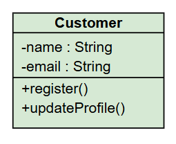
A class is drawn as a rectangle divided into up to three compartments:
- Class name (mandatory)
- Attributes (optional)
- Operations (optional)
Example:
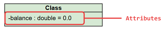
Attributes
Attributes describe the state of an object.
Syntax:
visibility name : type = default
Visibility symbols:
+public-private#protected
Example:
Operations represent the behavior or services the class provides.
Syntax:
Example:

Relationship Types in Class Diagrams
The power of a Class Diagram comes from the connections between classes. The most common relationship types describe how objects interact or rely on each other.
Association
An association shows a structural link between classes.
- Can include roles, multiplicities, or navigability.
- Represents stable, long-term connection.
Example:
A Customer places many Orders.
Aggregation
Aggregation represents a “whole–part” relationship where the part can exist independently.
Marked with a hollow diamond at the whole side.
Example:
A Team has multiple Players, but players can exist outside the team.
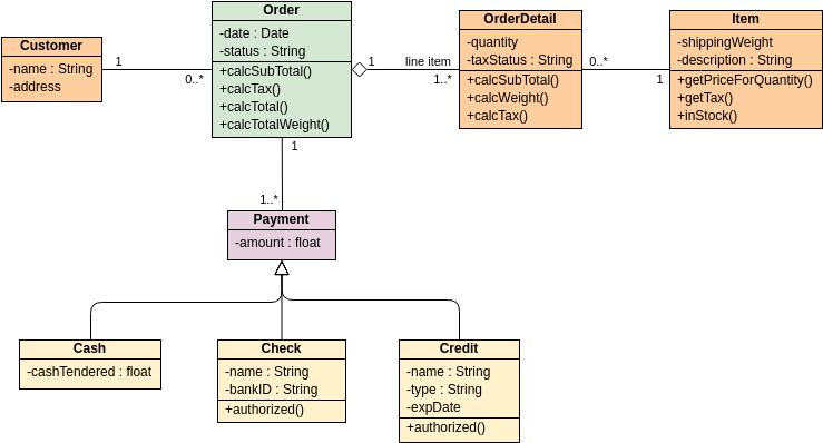
Composition
A stronger form of aggregation where the part’s lifecycle depends on the whole.
Marked with a filled diamond.
Example:
An Order contains OrderLine items, and removing the order removes all its lines.
Generalization (Inheritance)
Shows that one class extends another.
- Arrow points toward the parent class.
- Used for shared attributes and polymorphic behavior.
Example:SavingAccount → Account
Dependency
Indicates that one class uses or relies on another temporarily (e.g., a parameter).
Often shown with a dashed arrow.
Realization
Used when a class implements an interface.
Practical Object-Oriented Examples
Below are simple but realistic scenarios that demonstrate how Class Diagram syntax appears in real design work.
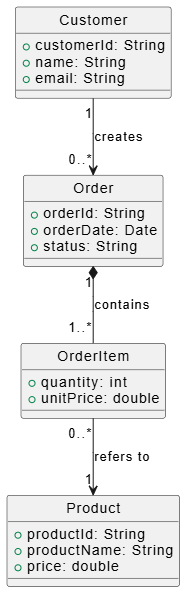
Example: E-Commerce Ordering System
Classes:
- Customer
- Order
- OrderItem
- Product
Key relationships:
- Customer creates Order (association)
- Order composes OrderItem (composition)
- OrderItem refers to Product (association)
This structure clearly shows:
- The ownership of order line items
- The connection between ordered items and product data
- The role of the customer in the transaction process
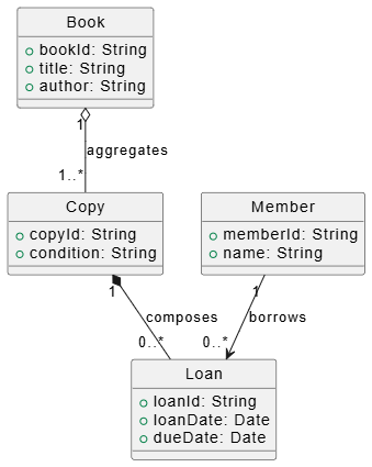
Example: Library Management
Classes:
- Book
- Copy
- Member
- Loan
Relationships:
- Book aggregates Copy (copies exist independently of the book metadata)
- Copy composes Loan (loans do not exist without the copy being loaned)
- Member borrows Loan (association)
This model separates the abstract concept of a book from physical copies.
Why Class Diagrams Matter
Class Diagrams remain at the core of UML because they help you:
- Clarify the object-oriented structure before coding
- Refine responsibilities and boundaries
- Detect missing concepts or overly complex designs
- Communicate technical ideas effectively
- Keep documentation aligned with implementation
Whether you use UML frequently or occasionally, mastering class diagram notation helps build stronger designs.
For further explanation of UML and how AI supports its visualization, refer to our UML resource hub.
This post is also available in Deutsch, Español, فارسی, Français, English, Bahasa Indonesia, 日本語, Polski, Portuguese, Ру́сский, Việt Nam, 简体中文 and 繁體中文.