
📋 Introduction
Business Process Model and Notation (BPMN) 2.0 represents a significant evolution in business process modeling, introducing powerful new notations for choreography, conversations, and complex message flows. This comprehensive guide walks you through creating a stand-alone Choreography Diagram using Visual Paradigm, one of the most intuitive and feature-rich BPMN modeling tools available.
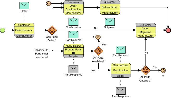
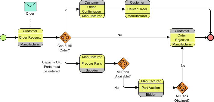
By the end of this tutorial, you’ll be able to create professional BPMN 2.0 diagrams like this:
💡 Who is this for? Business analysts, process architects, product managers, and anyone looking to visualize complex multi-party business interactions with industry-standard notation.
🛠️ Prerequisites & Tool Setup
Required Software
-
Visual Paradigm (Enterprise, Professional, Standard, or Modeler edition)
-
All editions support BPMN 2.0 modeling
Recommended Knowledge
-
Basic understanding of business process concepts
-
Familiarity with BPMN fundamentals (events, activities, gateways)
-
No prior Visual Paradigm experience required!
User Experience Tip 💭
“As someone who’s evaluated multiple BPMN tools, I found Visual Paradigm’s Resource Catalog to be a game-changer. Instead of hunting through toolbars, you can create connected elements in just 2-3 clicks. This dramatically speeds up diagram creation and reduces context-switching.”
🚀 Step-by-Step Tutorial: Building Your First BPMN 2.0 Choreography Diagram
Phase 1: Project & Model Setup
Step 1: Create a New Project
-
Select Project > New from the application toolbar
-
In the New Project window, enter
Tutorialas the project name -
Click Create Blank Project
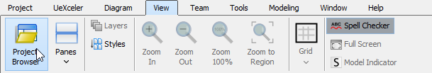
Step 2: Open Project Browser
-
Select View > Project Browser from the toolbar
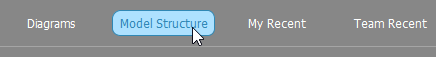
Step 3: Navigate to Model Structure
-
In the Project Browser, open the Model Structure page
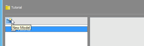
Step 4: Create a New Model
-
Click the New Model button at the top of the model list
-
Name the model
Salesand click OK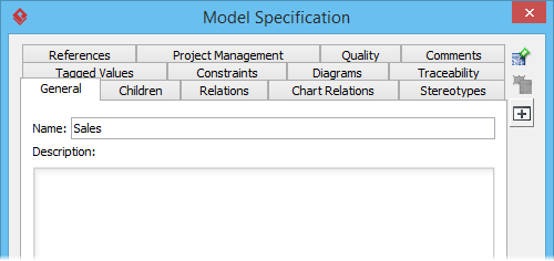
Phase 2: Creating Pools (Participants)
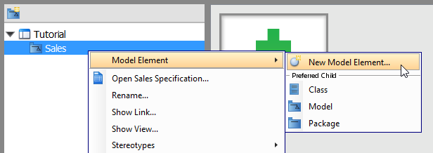
Step 5: Create the Customer Pool
-
Right-click on the Sales model → Model Element > New Model Element…
-
In the New Model Element window, type
Poin the search field to find Pool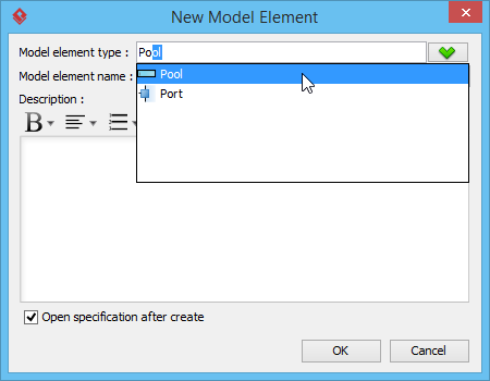
-
Enter
Customeras the Model element name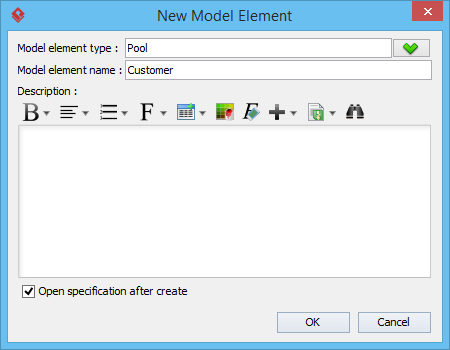
-
⚠️ Pro Tip: Uncheck Open specification after create to speed up bulk creation
-
Click OK
Step 6: Create Additional Pools
Repeat Step 5 to create these additional pools:
-
Bidder -
Manufacturer -
Supplier
🎯 User Experience Insight: Creating pools at the model level (rather than on the diagram) keeps your diagram canvas clean and allows you to reuse participants across multiple diagrams. This is especially valuable for enterprise-scale process architectures.
Phase 3: Building the Diagram Canvas
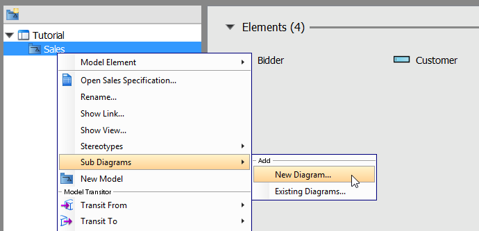
Step 7: Create the Business Process Diagram
-
Right-click on the Sales model → Sub Diagrams > New Diagram…
-
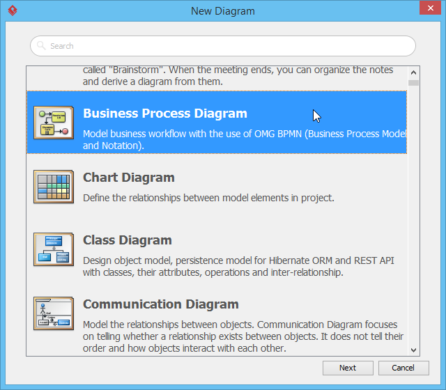
In the New Diagram window:
-
Select Business Process Diagram
-
Click Next
-
Keep the default diagram name or customize it
-
Click OK
-
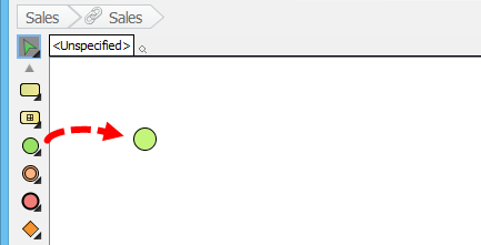
Step 8: Add the Start Event
-
Select the Start Event tool from the diagram toolbar
-
Click on the empty diagram area to place it
Phase 4: Creating Choreography Tasks
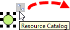
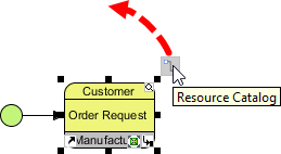
Step 9: Add Your First Choreography Task
-
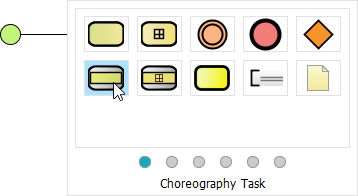
Click on the start event and drag out the Resource Catalog icon (the small square with arrows)
-
Release the mouse on a blank area and select Choreography Task
-
Enter
Order Requestas the task name and press Enter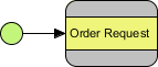
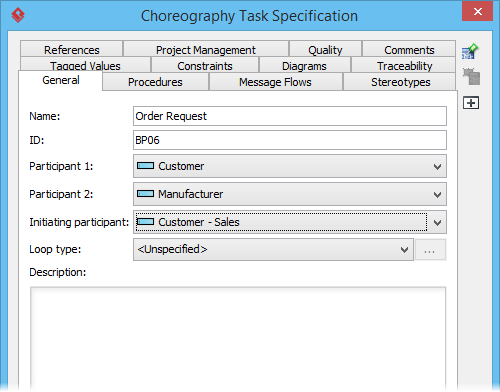
Step 10: Configure Task Participants
-
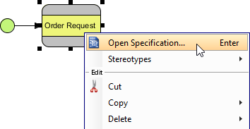
Right-click on Order Request → Open Specification…
-
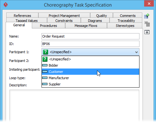
In the specification dialog:
-
Set Participant 1:
Customer -
Set Participant 2:
Manufacturer -
Set Initiating participant:
Customer
-
-
Click OK
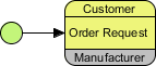
✨ Visual Feedback: Notice how the initiating participant (Customer) appears in the same color as the task background, while the non-initiating participant (Manufacturer) appears in gray. This visual distinction is automatic and helps stakeholders quickly understand interaction dynamics.
Phase 5: Adding Message Flows
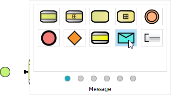
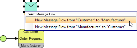
Step 11: Create a Message from Customer to Manufacturer
-
Click on Order Request and drag out the Resource Catalog
-
Release above the choreography task and select Message
-
Select New Message Flow from “Customer” to “Manufacturer”
-
Name the message
Orderand press Enter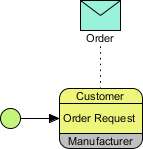
🔍 BPMN 2.0 Note: Message flows (dashed lines with open arrowheads) represent communication between participants, while sequence flows (solid lines) represent order of execution within a participant. Keeping these distinct is crucial for accurate modeling.
Phase 6: Adding Decision Logic with Gateways
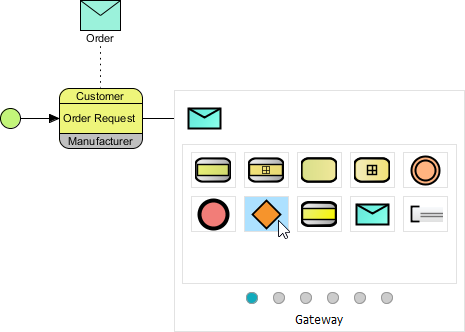
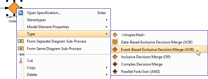
Step 12: Create an Event-Based Exclusive Gateway
-
Click on Order Request → drag Resource Catalog → release in empty space
-
Select Gateway from the catalog
-
Name it
Can Fulfill Order?(use Alt+Enter for line breaks if needed)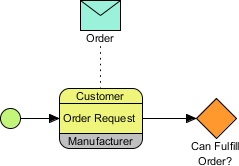
-
Right-click the gateway → Type > Event-Based Exclusive Decision/Merge (XOR)
Step 13: Expand the Diagram
Continue building the diagram following the pattern above. Your intermediate result should look like:
Phase 7: Advanced Patterns
Step 14: Multi-Instance Loop for Parallel Activities
Some activities may need to run multiple times concurrently (e.g., procuring parts from multiple suppliers).
-
Right-click on Procure Parts task → Open specification…
-
In the Loop type dropdown, select Multi-Instance Loop
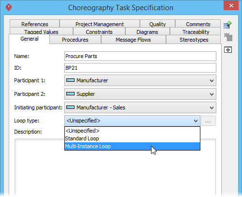
-
Click OK
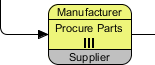
✅ Result: The task now displays the multi-instance marker (three vertical lines), signaling parallel execution to stakeholders.
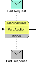
Step 15: Bidirectional Messaging (Manufacturer ↔ Bidder)
-
Using Resource Catalog on Part Auction task, create a Message
-
Select New Message Flow from “Manufacturer” to “Bidder”
-
Name it
Part Request -
Repeat to create the return message:
-
Select New Message Flow from “Bidder” to “Manufacturer”
-
Name it
Part Response
-
🎨 Visual Design Tip: Notice how the message from Bidder→Manufacturer appears in a different color. This reflects Bidder’s role as a non-initiating participant in that choreography context—a subtle but powerful visual cue for process analysts.
Step 16: Simplifying Complex Flows with Link Events
When “true” paths would create diagram clutter, use Link Intermediate Events to represent logical connections without crossing lines.
-
From the All Parts Available? gateway, use Resource Catalog to add an Intermediate Event
-
Name it
Aand connect with aYeslabeled sequence flow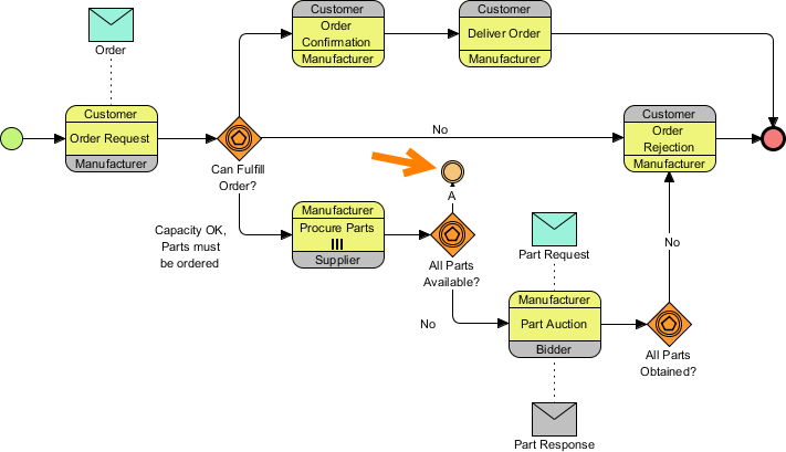
-
Right-click the event → Trigger > Link Trigger
-
Repeat for the All Parts Obtained? gateway
-
From the diagram toolbar, select Link Intermediate Event
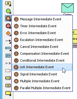
-
Place a matching
Alink event near Order Confirmation and connect it
🧭 Best Practice: Always use matching names for link event pairs (e.g., both named “A”). Visual Paradigm will automatically validate the pairing, preventing broken process logic.
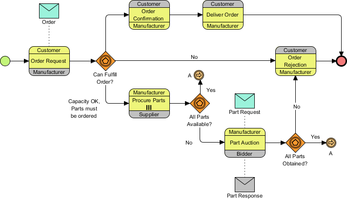
Step 17: Final Touches
Complete the remaining messages and connections. Your final diagram should match:
💡 Pro Tips & User Experience Insights
🎯 Efficiency Boosters
| Feature | Benefit | How to Access |
|---|---|---|
| Resource Catalog | Create connected elements in 2 clicks | Drag from any element |
| Model-Level Pools | Reuse participants across diagrams | Project Browser → Model Structure |
| Alt+Enter | Format multi-line labels | While editing element name |
| Link Events | Reduce diagram clutter | Diagram toolbar → Intermediate Event |
🎨 Visual Design Recommendations
-
Consistent Naming: Use question format for gateways (
Can Fulfill Order?) to clarify decision logic -
Color Coding: Leverage Visual Paradigm’s automatic participant coloring—don’t override unless necessary
-
Spacing: Leave 1.5-2x element height between components for readability
-
Alignment: Use Diagram > Arrange > Align for professional layout
🔧 Troubleshooting Common Issues
| Issue | Solution |
|---|---|
| Message flow won’t connect to choreography task | Ensure you’re dragging from the task’s message band (thin colored strip), not the main body |
| Gateway type doesn’t match BPMN spec | Right-click → Type to explicitly set XOR, AND, OR, or Event-Based |
| Multi-instance marker not appearing | Verify loop type is set in task specification, not just visually added |
| Link events not pairing | Confirm both events have identical names and are set to Link Trigger |
🔄 Collaboration & Export
-
Share with Stakeholders: Export as PNG/PDF via Diagram > Export
-
Version Control: Use Project > Save As Template for reusable process patterns
-
Documentation: Add descriptions in element specifications for auto-generated reports
-
Integration: Export to BPEL or generate executable workflows (Enterprise edition)
📚 Official Visual Paradigm Resources
- BPMN Notation Overview – Visual Paradigm Guide: This is a full notation guide that provides a list of BPMN symbols with clear explanations and diagram examples.
- What is BPMN? – Visual Paradigm Guide: An introductory guide explaining the purpose, structure, and benefits of BPMN in business process design.
- How to Draw a BPMN Diagram – Visual Paradigm Tutorial: A step-by-step tutorial on creating professional diagrams using an intuitive interface and modeling best practices.
- Understanding Pools and Lanes in BPMN – Visual Paradigm User Guide: A detailed explanation of how to use pools and lanes to represent different departments, organizations, or roles within a process.
- How to Perform Gap Analysis with BPMN? – Visual Paradigm: A guide that teaches how to use BPMN to identify discrepancies between current and future states during business analysis.
- BPMN – A Comprehensive Guide – Visual Paradigm Guides: This article discusses the vision behind BPMN 2.0, aiming to establish a unified specification for notation, metamodels, and interchange.
- Integrating BPMN and UML for Enhanced Modeling: A resource explaining how to combine BPMN and UML for more effective business and system modeling.
- How to Animate Business Processes with Visual Paradigm: A tutorial on creating dynamic, animated business process diagrams for improved visualization and communication.
- BPMN Activity Types Explained – Visual Paradigm: An article explaining that a BPMN Activity is “work” performed in a process, which can be atomic tasks or decomposable sub-processes.
- How to Create a BPMN Conversation Diagram in Visual Paradigm: A comprehensive guide on creating and using Conversation Diagrams to model interactions between different business partners.
✅ Conclusion
Creating BPMN 2.0 choreography diagrams in Visual Paradigm combines standards compliance with intuitive usability. By following this guide, you’ve learned to:
✅ Structure multi-participant processes with pools and choreography tasks
✅ Model complex message exchanges with proper flow semantics
✅ Apply advanced patterns like multi-instance loops and link events
✅ Maintain diagram clarity while representing sophisticated business logic
🌟 Final Thought: The real power of BPMN 2.0 isn’t just in drawing pretty diagrams—it’s in creating a shared language between business stakeholders and technical teams. Visual Paradigm’s tooling removes the friction, letting you focus on what matters: designing processes that drive real business value.
📌 Bookmark this guide! Revisit it as you tackle more complex scenarios like event sub-processes, transaction compensation, or BPMN-DMN integration. Happy modeling! 🎨🔄