
Introduction
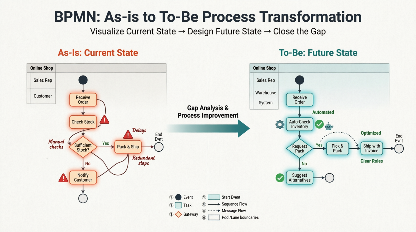
Developing and populating As-Is and To-Be BPMN diagrams is an effective technique for turning a vision into results. The As-Is diagram offers a detailed overview of the current state of the organization’s process, culture, and capabilities. The To-Be diagram, on the other hand, provides an overview of the future state, outlining how the organization’s process, culture, and capabilities will appear in the future. By creating these diagrams, organizations can analyze and identify gaps between the current and desired states and initiate business process reengineering or improvement initiatives to close these gaps.
PDF Download Compatible: Enterprise, Professional, Standard
Understanding BPMN: Notation, Elements, and Key Concepts
What is BPMN?
Business Process Model and Notation (BPMN) is a standardized graphical language for documenting, analyzing, and improving business processes [[28]]. The primary goal of BPMN is to provide a notation that is readily understandable by all business users—from business analysts who create initial drafts, to technical developers who implement the technology, to business people who manage and monitor processes [[1]].
BPMN 2.0, the current specification released in December 2013, has been formally published by ISO as standard ISO/IEC 19510 [[1]].
The Four Core Categories of BPMN Elements
BPMN organizes graphical elements into four basic categories to help modelers create clear, understandable diagrams [[1]]:
1. Flow Objects
Flow objects are the main describing elements within BPMN and consist of three core elements [[19]]:
| Element | Symbol | Description |
|---|---|---|
| Event | ○ Circle | Something that “happens” during a process. Events affect flow and usually have a cause (trigger) or impact (result). Three types: Start, Intermediate, and End [[1]]. |
| Activity | ▭ Rounded rectangle | Generic term for work performed. Can be atomic (Task) or compound (Sub-Process, distinguished by a + sign) [[1]]. |
| Gateway | ◇ Diamond | Controls divergence and convergence of Sequence Flow. Determines decisions, forking, merging, and joining of paths [[1]]. |
Gateway Types:
-
Exclusive Gateway (XOR): Follow only one path based on a condition
-
Inclusive Gateway (OR): Follow one or more paths based on conditions
-
Parallel Gateway (AND): Follow all paths simultaneously [[1]]
2. Connecting Objects
These connectors link flow objects to create the process structure [[1]]:
| Connector | Symbol | Purpose |
|---|---|---|
| Sequence Flow | → Solid line with arrow | Shows the order activities are performed in a process [[1]] |
| Message Flow | ⇢ Dashed line with open arrowhead | Symbolizes information flow across organizational boundaries [[1]] |
| Association | ⤏ Dotted line | Connects artifacts to flow objects; shows relationships [[1]] |
3. Swimlanes
Swimlanes organize activities into visual categories to illustrate responsibilities [[2]]:
| Element | Description |
|---|---|
| Pool | Represents a Participant in a Process; acts as a graphical container for partitioning activities, typically in B2B contexts [[1]] |
| Lane | A sub-partition within a Pool that extends its entire length; used to organize and categorize activities by role, department, or system [[1]] |
4. Artifacts
Artifacts provide additional context without affecting Sequence Flow [[1]]:
| Artifact | Symbol | Purpose |
|---|---|---|
| Data Object | 📄 Page icon | Shows how data is required or produced by activities [[1]] |
| Data Store | 🗄️ Cylinder | Represents persistent data storage the process can read/write [[1]] |
| Group | ⬚ Dashed rounded rectangle | Used for documentation or analysis; does not affect flow [[1]] |
| Annotation | 📝 Note icon | Provides additional explanatory text for diagram readers [[1]] |
Event Types and Markers
BPMN events can be enhanced with internal markers to indicate triggers or results [[1]]:
| Event Type | Start | Intermediate | End |
|---|---|---|---|
| None | ○ | — | ● |
| Message | ○📧 | ○○📧 | ●📧 |
| Timer | ○🕐 | ○○🕐 | — |
| Error | — | ○○⚡ (boundary) | ●⚡ |
| Signal | ○△ | ○○△ | ●△ |
| Conditional | ○📋 | ○○📋 | — |
| Escalation | — | ○○↑ | ●↑ |
| Termination | — | — | ●● |
Note: Intermediate events can be catching (double circle) or throwing (filled marker); boundary events can be interrupting (solid) or non-interrupting (dashed) [[1]].
What is an As-Is Process?
An As-Is business process provides a comprehensive overview of a company’s current processes, culture, and capabilities. It documents how work is currently done and how information flows throughout the organization. The primary purpose of an As-Is business process is to establish a baseline for identifying areas of improvement, optimizing resource utilization, and ultimately boosting efficiency and productivity. By understanding the current state of operations, organizations can develop strategies to eliminate bottlenecks, reduce waste, and enhance overall business processes.
What is a To-Be Process?
A To-Be business process outlines the future state of a company’s processes, culture, and capabilities. It serves as a roadmap for change, clearly defining the organization’s goals and what it needs to do to achieve them. The purpose of a To-Be process is to provide a clear vision of the future and to identify the steps required to get there. This allows organizations to prioritize and focus on the most critical changes needed to close the gap between their current and desired states.
Software Tool We’ll Be Using
In this tutorial, we will use Visual Paradigm to create BPMN-compliant business process diagrams. Visual Paradigm provides a robust set of tools for capturing current business processes, designing improvements, and identifying the differences between the “as-is” and “to-be” states.
Capturing the Current Process in an As-Is Model
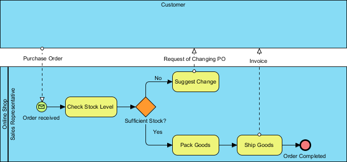
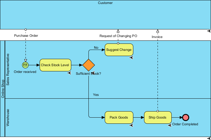
Let’s consider an online shop as an example. The process begins when a sales representative receives a purchase order and checks the stock level. If there is enough stock to fulfill the order, the sales representative packs the items and ships them with an invoice. If there is insufficient stock, the sales representative informs the customer and suggests modifying the order. This example highlights the importance of monitoring stock levels to ensure timely and efficient order fulfillment.
We will not cover the basics of drawing a business process diagram using Business Process Modeling Notation (BPMN) in this tutorial, as we have another tutorial that covers this topic. We also have a video tutorial called Introduction to BPMN – Swimlanes available for you.
Once you have documented your existing business process, you can create a To-Be process model by considering the necessary improvements. Follow the steps below to see how this works.
-
Download Online-Shopping.vpp. You can also find this file at the bottom of this tutorial.
-
Open the downloaded .vpp file in Visual Paradigm by selecting Project > Open from the application toolbar.
-
Open the Project Browser by selecting View > Project Browser from the application toolbar.
-
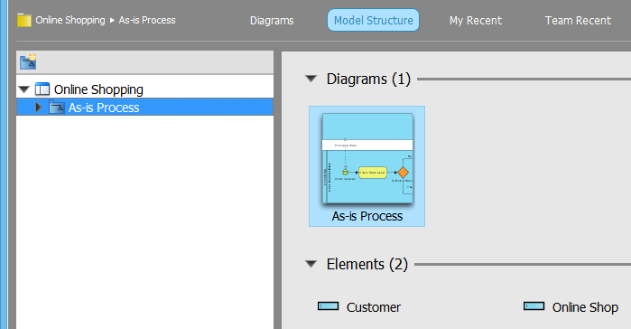
Navigate to the Model Structure tab.

-
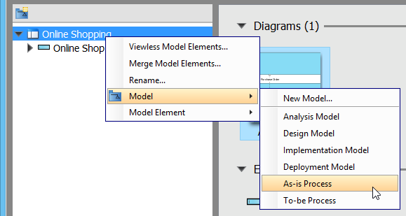
Right-click on the project root node in the tree on the left and select Model > As-Is Process from the popup menu.
-
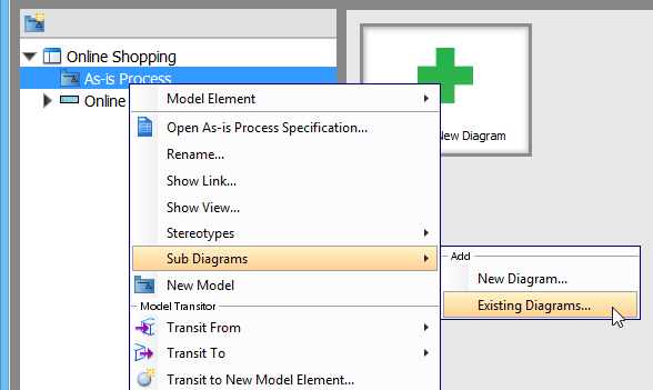
Right-click on As-Is Process and select Sub Diagrams > Existing Diagrams… from the popup menu.
-
In the Add Sub Diagram window, select the business process diagram and click OK.
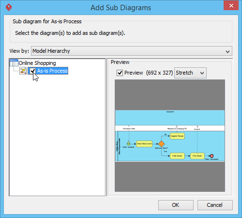
Your existing process is now contained within the As-Is Process model.
Re-designing and Enhancing the Process in a To-Be Model
Let’s assume our business has grown significantly, and we have a new warehouse to manage our inventory. To make the most of our new resources, we need to optimize our existing process. We will demonstrate how to depict this improvement by creating a To-Be process diagram.
-
Open the business process diagram by double-clicking its thumbnail in the Project Browser.
-
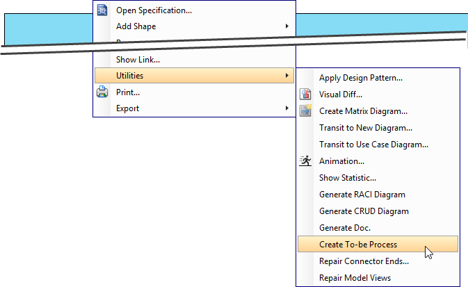
Create a To-Be process diagram from the current process diagram. Right-click on any empty space in the As-Is process diagram and select Utilities > Create To-be Process.
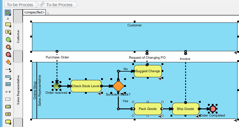
A new diagram will be created, containing the To-Be process.
Note: All model elements in the new diagram are selected by default. To deselect them, click on any empty space in the background.
-
Add a new lane to the Online Shop pool and name it Warehouse. In the Sales Representative lane, select the Pack Goods, Ship Goods, and Order completed tasks and drag them into the Warehouse lane. Your diagram should now look like this:
-
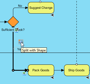
Next, we will insert a task between the Sufficient Stock? gateway and the Pack Goods task. Hover your mouse over the Yes flow and click on the Split with Shape resource button.
-
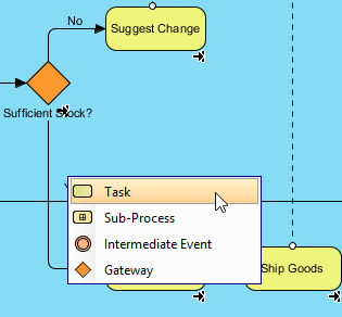
Select Task from the resource catalog.
-
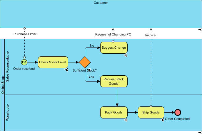
Name the new task Request Pack Goods. The completed To-Be process diagram should look like this:
Comparing Changes Between As-Is and To-Be Processes
To visually compare the differences between two diagrams, we can use a feature called Visual Diff.
-
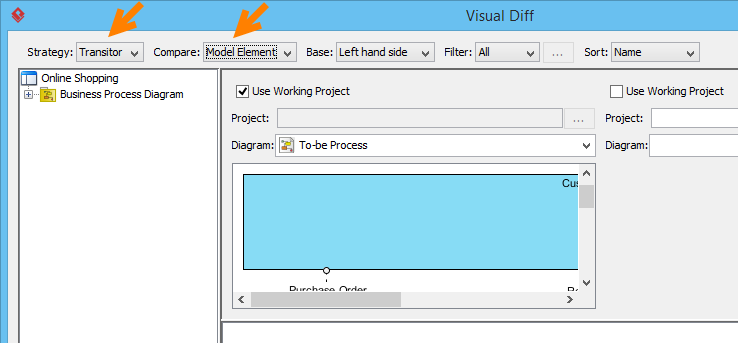
Select Modeling > Visual Diff… from the application toolbar.
-
In the Visual Diff window, select Transitor as the Strategy. For Compare, choose Model Element to compare the diagrams at the model element level.
-
Check the Use Working Project checkbox. Select As-Is Process on the left and To-Be Process on the right. The comparison will be triggered automatically.
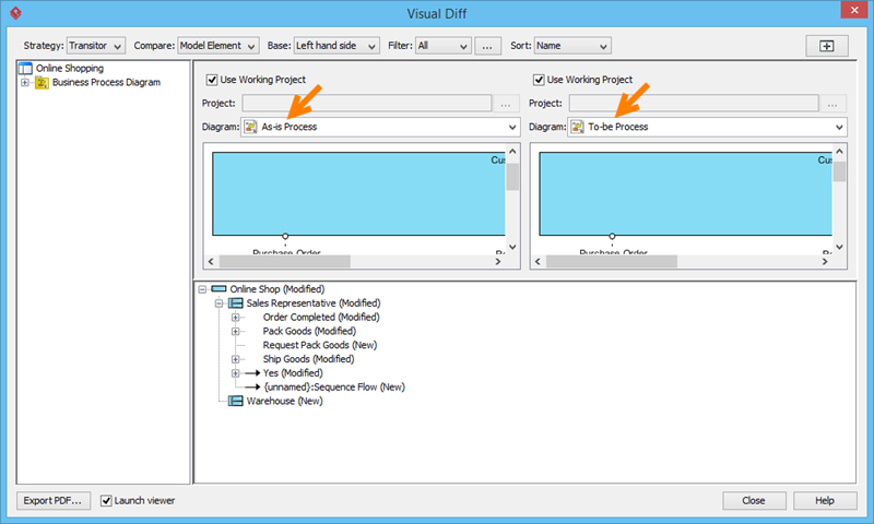
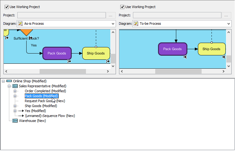
The list below the diagrams shows the differences. For example, the entry Pack Goods (Modified) indicates that changes were made to the Pack Goods task. Clicking on this entry will highlight the corresponding changes in purple in the diagrams.
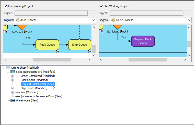
New tasks are also identified. Remember that we added a new task for the sales representative to request packing? That change is also highlighted in the list.
Best Practices for As-Is and To-Be Modeling
For As-Is Documentation:
-
Interview stakeholders: Gather input from people who actually perform the work
-
Validate with data: Use metrics, logs, and observations to confirm process steps
-
Document exceptions: Capture error paths and edge cases, not just the “happy path”
-
Keep it current: Update As-Is models when processes change to maintain accuracy
For To-Be Design:
-
Focus on outcomes: Start with business goals, then design processes to achieve them
-
Involve implementers: Include IT and operations teams early to ensure feasibility
-
Prioritize changes: Not all gaps need immediate closure; focus on high-impact improvements
-
Plan transitions: Define how you’ll move from As-Is to To-Be (phased rollout, training, etc.)
For BPMN Modeling:
-
Use consistent naming: Apply clear, action-oriented labels to tasks and events
-
Limit complexity: Break large processes into sub-processes for readability
-
Leverage swimlanes: Use lanes to clarify roles and responsibilities
-
Annotate strategically: Add notes only where needed to avoid clutter
Watch This Tutorial on YouTube
Reference List
- As-Is to To-Be Business Process Tutorial: Comprehensive tutorial on developing As-Is and To-Be BPMN diagrams using Visual Paradigm, including step-by-step instructions for capturing current processes, redesigning for future states, and comparing changes.
- Visual Paradigm Enterprise Edition: Information about Visual Paradigm’s Enterprise edition, which supports advanced BPMN modeling, collaboration, and enterprise-scale process management capabilities.
- Visual Paradigm Professional Edition: Details on Visual Paradigm’s Professional edition, offering robust BPMN diagramming tools suitable for business analysts and process improvement teams.
- Visual Paradigm Standard Edition: Overview of Visual Paradigm’s Standard edition, providing essential BPMN modeling features for individual practitioners and small teams.
- Visual Paradigm Homepage: Official website for Visual Paradigm, featuring BPMN diagramming tools, tutorials, and resources for business process modeling and management.
- BPMN Diagram and Tools Feature Page: Detailed information about Visual Paradigm’s BPMN diagramming capabilities, including supported notation elements, collaboration features, and export options.
- BPMN Basics Tutorial: Foundational tutorial covering BPMN notation basics, ideal for beginners learning to create business process diagrams.
- Introduction to BPMN – Swimlanes (Video): Video tutorial demonstrating how to use swimlanes in BPMN diagrams to organize activities by role, department, or system.
- BPMN Notation Overview – Visual Paradigm: Full BPMN notation guide with clear explanations of symbols, elements, and diagram examples for creating standards-compliant business process models [[1]].