


What is BPMN
The Business Process Management Initiative (BPMI) has developed a standard Business Process Modeling Notation (BPMN). The BPMN 1.0 specification was released to the public in May, 2004. This specification represents more than two years of effort by the BPMI Notation Working Group. A BPMN Specification document was released by OMG in February, 2006. Version 2.0 of BPMN was developed in 2010, and the actual version of the specification was released in December 2013.
Goal of BPMN
The primary goal of the BPMN effort was to provide a notation that is readily understandable by all business users, from the business analysts that create the initial drafts of the processes, to the technical developers responsible for implementing the technology that will perform those processes, and finally, to the business people who will manage and monitor those processes.
BPMN Implementation
BPMN will also be supported with an internal model that will enable the generation of executable BPEL4WS. Thus, BPMN creates a standardized bridge for the gap between the business process design and process implementation.
A Simple BPMN
BPMN defines a Business Process Diagram (BPD), which is based on a flowcharting technique tailored for creating graphical models of business process operations. A Business Process Model, then, is a network of graphical objects, which are activities (i.e., work) and the flow controls that define their order of performance.
Key Concepts of BPMN
A BPD is made up of a set of graphical elements. These elements enable the easy development of simple diagrams that will look familiar to most business analysts (e.g., a flowchart diagram).
The elements were chosen to be distinguishable from each other and to utilize shapes that are familiar to most modelers. For example, activities are rectangles and decisions are diamonds. It should be emphasized that one of the drivers for the development of BPMN is to create a simple mechanism for creating business process models, while at the same time being able to handle the complexity inherent to business processes.
The approach taken to handle these two conflicting requirements was to organize the graphical aspects of the notation into specific categories. This provides a small set of notation categories so that the reader of a BPD can easily recognize the basic types of elements and understand the diagram. Within the basic categories of elements, additional variation and information can be added to support the requirements for complexity without dramatically changing the basic look-and-feel of the diagram.
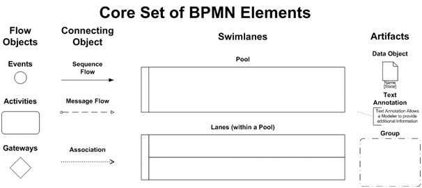
The four basic categories of elements are:
- Flow Objects (event / activity / Gateway)
- Connecting Objects (sequence flow / message flow / association)
- Swimlanes (pool / lane)
- Artifacts (Data Object / Group / Annotation)
Flow Objects A BPD has a small set of (three) core elements, which are the Flow Objects, so that modelers do not have to learn and recognize a large number of different shapes. The three Flow Objects are:
BPMN Flow Objects
A BPD has a small set of (three) core elements, which are:
Flow Objects, so that modelers do not have to learn and recognize a large number of different shapes. The three Flow Objects are:
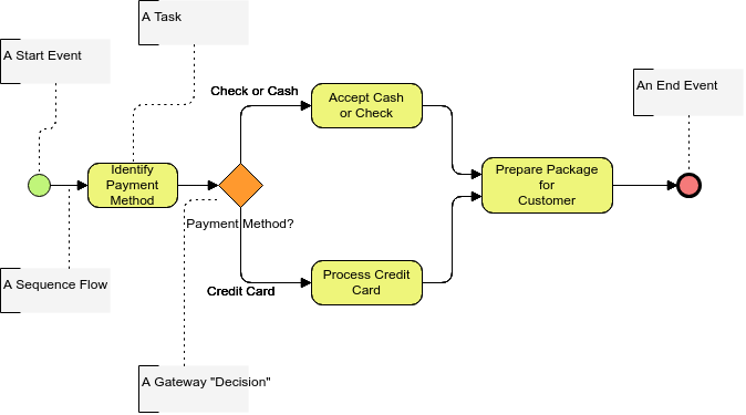
- An Event is represented by a circle and is something that “happens” during the course of a business process. These Events affect the flow of the process and usually have a cause (trigger) or an impact (result). Events are circles with open centers to allow internal markers to differentiate different triggers or results. There are three types of Events, based on when they affect the flow: Start, Intermediate, and End (see the figures to the right, respectively).

2. An Activity is represented by a rounded-corner rectangle (see the figure to the right) and is a generic term for work that company performs. An Activity can be atomic or nonatomic (compound). The types of Activities are: Task and Sub-Process. The Sub-Process is distinguished by a small plus sign in the bottom center of the shape.

3. A Gateway is represented by the familiar diamond shape (see the figure to the right) and is used to control the divergence and convergence of Sequence Flow. Thus, it will determine traditional decisions, as well as the forking, merging, and joining of paths. Internal Markers will indicate the type of behavior control.

BPMN Connecting Objects
The Flow Objects are connected together in a diagram to create the basic skeletal structure of a business process. There are three Connecting Objects that provide this function. These connectors are:
- A Sequence Flow is represented by a solid line with a solid arrowhead (see the figure to the right) and is used to show the order (the sequence) that activities will be performed in a Process. Note that the term “control flow” is generally not used in BPMN.

2. A Message Flow is represented by a dashed line with an open arrowhead (see the figure to the right) and is used to show the flow of messages between two separate Process Participants (business entities or business roles) that send and receive them. In BPMN, two separate Pools in the Diagram will represent the two Participants.
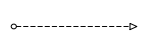
3. An Association is represented by a dotted line with a line arrowhead (see the figure to the right) and is used to associate data, text, and other Artifacts with flow objects. Associations are used to show the inputs and outputs of activities.

BPMN Diagram at a Glance
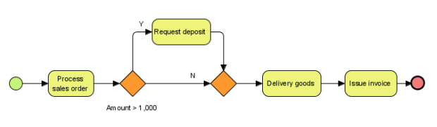
For modelers who require or desire a low level of precision to create process models for documentation and communication purposes, the core elements plus the connectors will provide the ability to easily create understandable diagrams (see Diagram below).
(Click and Open Diagram Instantly with Visual Paradigm Online)
For modelers who require a higher level of precision to create process models, which will be subject to detailed analysis or will be managed by Business Process Management System (BPMS), additional details can be added to the core elements and shown through Procurement and Financial Settlement (see Diagram below).
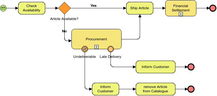
(Click and Open Diagram Instantly with Visual Paradigm Online)
BPMN Swimlanes
Many process modeling methodologies utilizes the concept of swimlanes as a mechanism to organize activities into separate visual categories in order to illustrate different functional capabilities or responsibilities. BPMN supports swimlanes with two main constructs. The two types of BPD swimlane objects are:
- A Pool represents a Participant in a Process. It is also acts as a graphical container for partitioning a set of activities from other Pools, usually in the context of B2B situations.
- A Lane is a sub-partition within a Pool and will extend the entire length of the Pool, either vertically or horizontally. Lanes are used to organize and categorize activities.
Example: To-be Process for Purchase Order Process based on As-is
his is a to-be process diagram example. Once the business process of your existing operation has been created, you can then derive the to-be process model by considering and projecting the necessary improvements or changes needed to be made based.
Use this BPMN diagram template to get started building your own. Customize the BPMN diagram to reflect your organization. Click Use this Template to start.
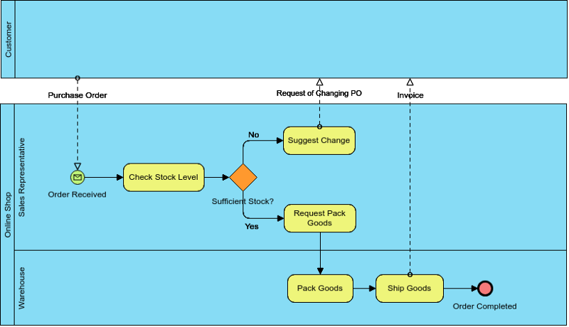
Pools are used when the diagram involves two separate business entities or participants (see Diagram below) and are physically separated in the diagram. The activities within separate Pools are considered self-contained Processes. Thus, the Sequence Flow may not cross the boundary of a Pool. Message Flow is defined as being the mechanism to show the communication between two participants, and, thus, must connect between two Pools (or the objects within the Pools).
Lanes are more closely related to the traditional swimlane process modeling methodologies. Lanes are often used to separate the activities associated with a specific company function or role (see Diagram below). Sequence Flow may cross the boundaries of Lanes within a Pool, but Message Flow may not be used between Flow Objects in Lanes of the same Pool.
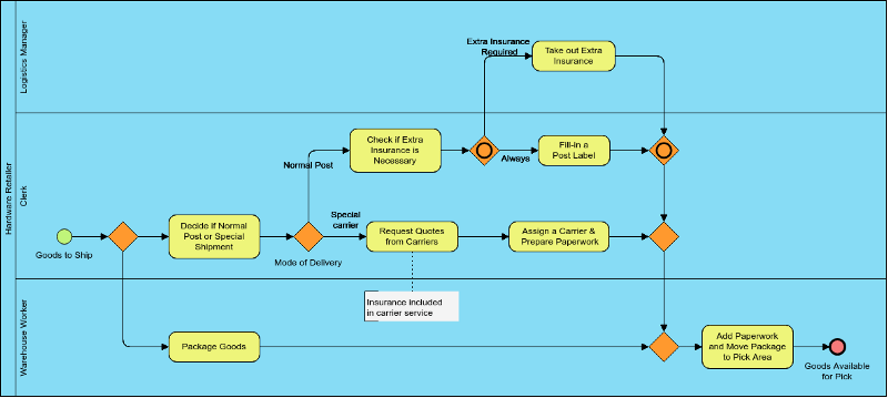
Example: Shipment Process of a Hardware Retailer
n this BPD example, we used only one pool and different lanes for the people involved in this process, which automatically means that we blank out the communication between those people: We just assume that they are communicating with each other somehow. If we had a process engine driving this process, that engine would assign user tasks and therefore be responsible for the communication between those people.
Use this BPMN diagram template and customize it to reflect your organization. Click Use this Template to start.
BPMN Artifacts
Artifacts BPMN was designed to allow modelers and modeling tools some flexibility in extending the basic notation and in providing the ability to additional context appropriate to a specific modeling situation, such as for a vertical market (e.g., insurance or banking). Any number of Artifacts can be added to a diagram as appropriate for the context of the business processes being modeled. The current version of the BPMN specification pre-defines only three types of BPD Artifacts, which are:
Data Objects are a mechanism to show how data is required or produced by activities. They are connected to activities through Associations.

A Group is represented by a rounded corner rectangle drawn with a dashed line . The grouping can be used for documentation or analysis purposes, but does not affect the Sequence Flow.

Annotations are a mechanism for a modeler to provide additional text information for the reader of a BPMN Diagram

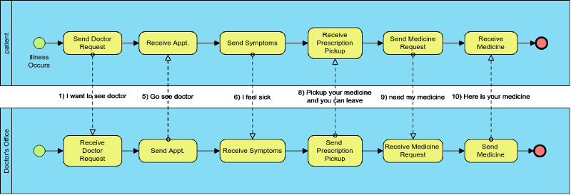
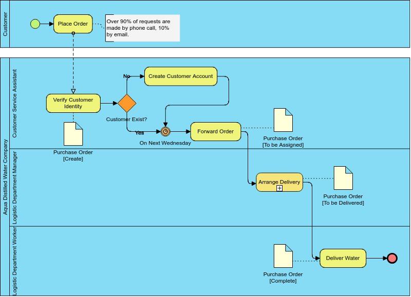
Example: Aqua Distilled Water Company
This is a simple BPMN example that shows the business process flow involved in delivering distilled water.
Use this BPMN diagram template as a starting point to create your own, or click Create Blank to start from scratch. (Click to Open / Edit Example)
Other Business Analysis Tools
- ArchiMate 3
- What is ArchiMate?
- Full ArchiMate Viewpoints Guide
- ArchiMate 3 Update
- What’s New in ArchiMate 3?
- Using ArchiMate Tool with TOGAF ADM
Business Process Modeling
Customer Journey Mapping
Business Diagramming Software
This post is also available in Deutsch, Español, فارسی, Français, English, Bahasa Indonesia, 日本語, Polski, Portuguese, Ру́сский, Việt Nam, 简体中文 and 繁體中文.