


Use case modeling is a useful tool for capturing requirements. It provides a graphical representation of the requirements of a software system.
With the publication of Ivar Jacobson’s (1991) book Object-Oriented Software Engineering, A Use-Case-Driven Approach, use case modeling effectively became a practical analysis technique”. Today, Jacobson continues to promote this approach to systems analysis and has upgraded it to Use Case 2.0, which is officially one of the 14 types of UML diagrams.
Because the use case model is simple in concept and appearance, it is relatively easy to discuss its correctness with non-technical personnel (such as customers).
A use case is not a procedure, process, or function.
The Elements of Use Case Diagram
The elements of a use case Diagram are the actors (external entities) and the use case itself. Broadly speaking, a use case is a functional unit (requirement) or service in a system.
Actor
An actor is any entity external to the design system, whether it is a person or another non-human entity. A user of a system is a typical example of an actor. Other types of actors include software systems that are being integrated with the current system (e.g., a database system), external hardware such as a sensor and so on. 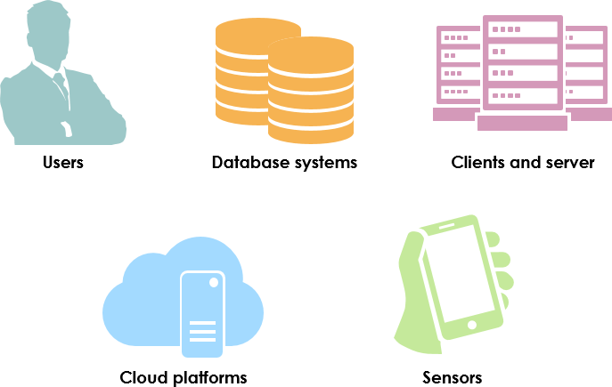
There are two notations in the UML specification:
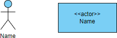
Using stickman for actors is more expressive, but can lead to confusion if the actor is not actually a person, but a machine or external device. The rectangle symbol is the standard UML notation for a class.
An Actor is Role Rather than a Real Person
An actor represents the role of the entity that interacts with the current system, not an instance. The actor notation indicates that the entity is a class instead of a read instance (i.e. a real user John or Mary). The reason why an actor is a type of a class is that it is not the actor himself/herself, but the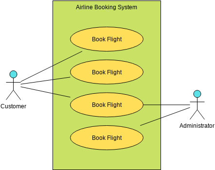 role he/she plays.
For example, an actor can represent a bank’s customers, rather than specifying a separate actor for each customer. Similarly, there may be another actor representing the bank manager. Interestingly, in the real world, the manager of a bank may also be a customer of the same bank. In other words, the same person plays the role of both customer and manager.
Primary Actor of a use case is the stakeholder that requires the system to provide its services. It has a goal associated with the system – a goal that can be satisfied by the operation of the system. The primary actor is usually, but not always, the actor that triggers the use case.
Secondary Actor is used by the system, but they do not interact with the system on their own. In other words, secondary actors do not initiate any use cases.
Use cases are usually initiated by the primary actors. The system uses a secondary actor such as a database through a set of use cases. The association between use cases and participants represents a two-way communication.
Thus, for each use case initiated by a primary actor, the connected use case must be responded to. Similarly, for each association between a secondary actor and a use case, the communication starts with the use case and the secondary actor should respond to the initiation.
Use Case
Use cases represent the functions (usually requirements) expected to be implemented by the system. The details of the use case, except its unique name, are not intuitively expressed in the diagram; These details are given in the use case description.
Use cases are usually initiated by key actors. The system uses database and other auxiliary participants through a set of use cases.
The association between use cases and actors represents two-way communication. Therefore, for each use case initiated by the main actor, the latter must be responded to. Similarly, for each association between the secondary actor and the use case, the communication starts with the use case, and the secondary actor should respond to the initiation.
System Boundary
The system boundary defines the system of interest in relation to the world around it.
Use Case Diagram Example: Airline Booking System
Use cases define interactions between external actors and the system to attain particular goals. A use case diagram contains four main components
In the use case diagram of a ticket booking system, the system is represented by boxes containing many different use cases. The primary actor is the customer and the secondary actor is the administrator. The customer initiates the use cases, such as booking, browsing and cancelling flights, while the administrator initiates the use cases, such as updating flight records, but is considered a secondary actor in the cancel flight use case, as she is only helping to complete the use cases initiated by the customer.

Edit this UML Use Case Diagram example
Structuring Use Cases
According to the application field and designer’s choice, a use case can be broken down into multiple use cases, which are connected through < < include > > or < < extend > > relationships.
Association Link represents a two-way communication between an actor and a use case, and is therefore a binary relationship. Since it is a two-way communication, for each use case initiated by a primary actor, that actor must get a response from the use case.
Similarly, for each communication between a use case and a secondary actor (initiated by the use case), the secondary actor must send a response back to the use case.
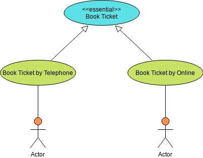
Generalization
The generalization represents the relationship between
- roles or
- use cases.
Edit this UML Use Case Diagram template
If two actors are connected by this relationship, then the actor (or use case) at the end of the arrow (connected to the bottom of the triangle) is a specialized version of the actor (or use case) at the other end.
Typically, the actor (or use case) at the bottom end (connected to the bottom of the triangle) is referred to as the specialized version of the actor (or use case) at the other end.
The generalization means that the specialized version has every feature of the general version, and possibly more.
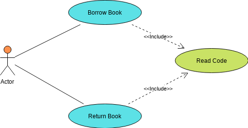
Include is a special type of relationship between two use cases. If a use case A includes another use case B, then the implementation of A requires the implementation of B to complete its task. However, B is independent of itself. That is, B does not need to know anything about A. B can also be included in any other use case.
Edit this Use Case Diagram example
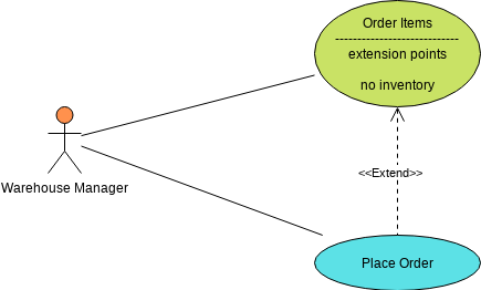
Extend is another special kind of relationship between two use cases. If a use case B extends another use case A, then the implementation of A can conditionally include the implementation of B to complete its task. That is, in some cases, A can complete its task without B. However, depending on the conditions described.
Edit this Use Case Diagram example
Use Case Diagram Notations
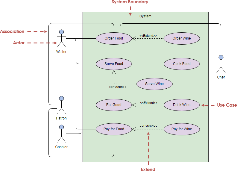
Edit this Use Case Diagram example online
9 Simple Steps for Performing Use Case Analysis
- Determine who will directly use the system. These people are the actors.
- Pick one of these actors.
- Define what that actor wants to do with the system. Each thing that the actor wants to do with the system becomes a use case.
- Repeat steps 2-3 for all other use cases
Identify the secondary roles and non-human role support for the use cases you have identified. - Draw the initial version of the use case, do not overcomplicate the use case relationships at this point
- Discuss and review with users to validate the goals of each use case (benefits of the proposed functionality) After modifications, you can continue to detail the use cases in steps 8 – 10
- For each use case, decide the most common process that the actor will follow when using the system. What would normally happen.
- Describe this basic process in the description of the use case.
- Once you are satisfied with the basic process, now consider alternative scenarios and add these as extended use cases.
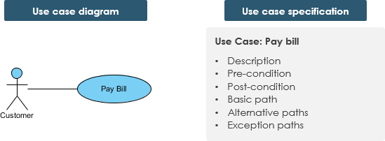
Use Case Model and Specification
It is not enough to just show the use case diagram in UML notation. Each use case is accompanied by text that explains the purpose of the use case and the functionality that is accomplished when the use case is executed.
A use case describes a task performed by an actor that produces a business value outcome for the enterprise. A use case can be visualized as a use case diagram or/and in a structured text specification format.
Use Case Scenarios
A use case consists of a number of scenarios, each representing a specific instance of the use case, corresponding to specific inputs from the actor or specific conditions in the environment. Each scenario describes an alternative way for the system to behave, or it may describe failures or exceptions.
A use case has:
- Only one goal
- A single starting point
- A single ending point
- Multiple paths for getting from start to finish
- i.e. Specify behavior for a variety of possible conditions
- Each conditions may require specific action(s)
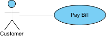
For Example – Customer pays bill:
There are multiple paths to achieve the goal:
- Telephone payment
- By mail
- In person
- by check
- by cash, etc.
A path that does not lead to the goal:
- Credit card is declined
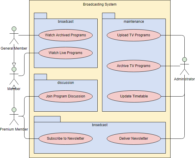
Grouping Use Cases with Packages
You can also: Draw packages for logical categorization of use cases into related subsystems.
Edit this Use Case Diagram example
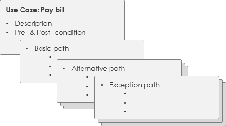
Detailed Use Case Specification
A detailed use case is a textual representation that describes a flow of events and other related use case information in a specific format. A standard use case template is often used to document the details of a use case
What is a Use Case Description
A use case description is a written description of the sequence of steps that an analyst performs to complete a complete system transaction. It is initiated by an actor, provides value to that actor, and is the goal of the actors working in the system.
Actor – Any person or system external to the system that uses or interacts with the system to achieve a goal. Each actor is given a role to represent their interaction with the solution. People actors should be named in the form of roles and should not be assigned actual names. Actors are generally categorized as primary, secondary, or stakeholder
Primary actor – The actor who initiates the use case.
Secondary actor – The actor who reacts or responds to the actions performed by the primary actor.
Stakeholders – off-stage actors who do not interact directly with the use case, but have an interest in the outcome of the use case.
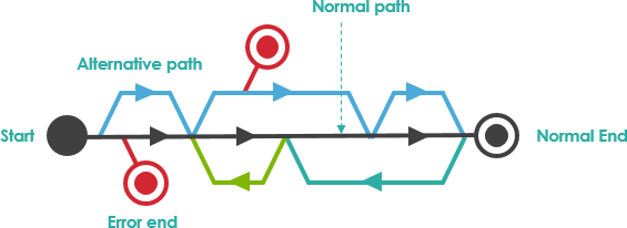
Flow of Event flow (path) – the sequence of steps that actors and solutions must take to execute a use case. In general, a use case consists of a primary success path (also called basic or primary), an alternate path, and an exception path.
The Normal path – the input from the actor and the response from the system – represents the most common success path for accomplishing the actor’s goals.
Alternate paths – inputs from the actor and system responses, representing the other less common paths to accomplish the actor’s goal
Exceptional paths – inputs from the actor and system response, representing unsuccessful paths when the actor’s goal cannot be achieved.
| Use Case Description | |
|---|---|
| Use Case Name: | Withdraw Cash |
| Actor(s): | Customer (primary), Banking System (secondary) |
| Summary Description: | Allows any bank customer to withdraw cash from their bank account. |
| Priority: | Must Have |
| Status: | Medium Level of details |
| Pre-Condition: | The bank customer has a card to insert into the ATM The ATM is online properly |
| Post-Condition(s): |
|
| Basic Path: |
|
| Alternative Paths: |
|
| Business Rules: |
|
| Non-Functional Requirements: |
|
Related Links
- What is Unified Modeling Language?
- Use Case Slide / Lecture Notes
- The Role of Use Cases in Requirements and Analysis Modeling
- A list of UML tools
- Try Visual Paradigm FREE
- Use Case – Notes for Training Couse
- How to Write Effective Use Cases?
- Book Chapter – PDF – Use Case Model: Writing Requirements in Context
This post is also available in Deutsch, Español, فارسی, Français, English, Bahasa Indonesia, 日本語, Polski, Portuguese, Ру́сский, Việt Nam, 简体中文 and 繁體中文.