


In the landscape of software development, a persistent challenge remains the translation of abstract business requirements into concrete technical implementation. Developers often find themselves interpreting complex workflows that are documented in natural language, leading to misalignment and rework. Business Process Model and Notation (BPMN) serves as a standardized graphical notation to specify business processes in a business process model. For developers, understanding this notation is not merely about drawing diagrams; it is about creating a shared language that ensures the code written actually solves the business problem intended.
This guide explores how BPMN 2.0 standards function as a bridge between the business logic held by stakeholders and the code logic held by engineering teams. By adopting these modeling practices, development teams can reduce ambiguity, improve testing coverage, and streamline the deployment of complex workflows without relying on specific proprietary tools. The focus here is on the technical application of the standard to enhance system architecture and maintainability.
Understanding BPMN 2.0 Standards 📐
BPMN 2.0 is a standard created by the Object Management Group (OMG). It is designed to be understood by all business stakeholders, from process analysts to software architects. Unlike proprietary diagramming tools that lock users into specific ecosystems, BPMN defines a set of visual elements and their execution semantics that are platform-agnostic.
For a developer, the value lies in the executable nature of the notation. A diagram is not just documentation; it represents a state machine or a workflow definition that can be deployed to a runtime engine. The standard defines how these elements interact, providing a deterministic behavior that aligns with programming logic.
- Standardization: Ensures that a process model created by one team can be interpreted by another without loss of meaning.
- Executable Semantics: Defines exactly what happens when an event is triggered, allowing for direct mapping to code logic.
- Human Readability: Visualizes complex logic that might be obscured in raw code, making it easier for non-technical stakeholders to validate requirements.
Core Building Blocks of Process Modeling 🧱
To model a process effectively, developers must understand the fundamental shapes used in BPMN. These shapes represent specific behaviors and states within the system. Each shape has a defined input and output behavior that corresponds to programming constructs.
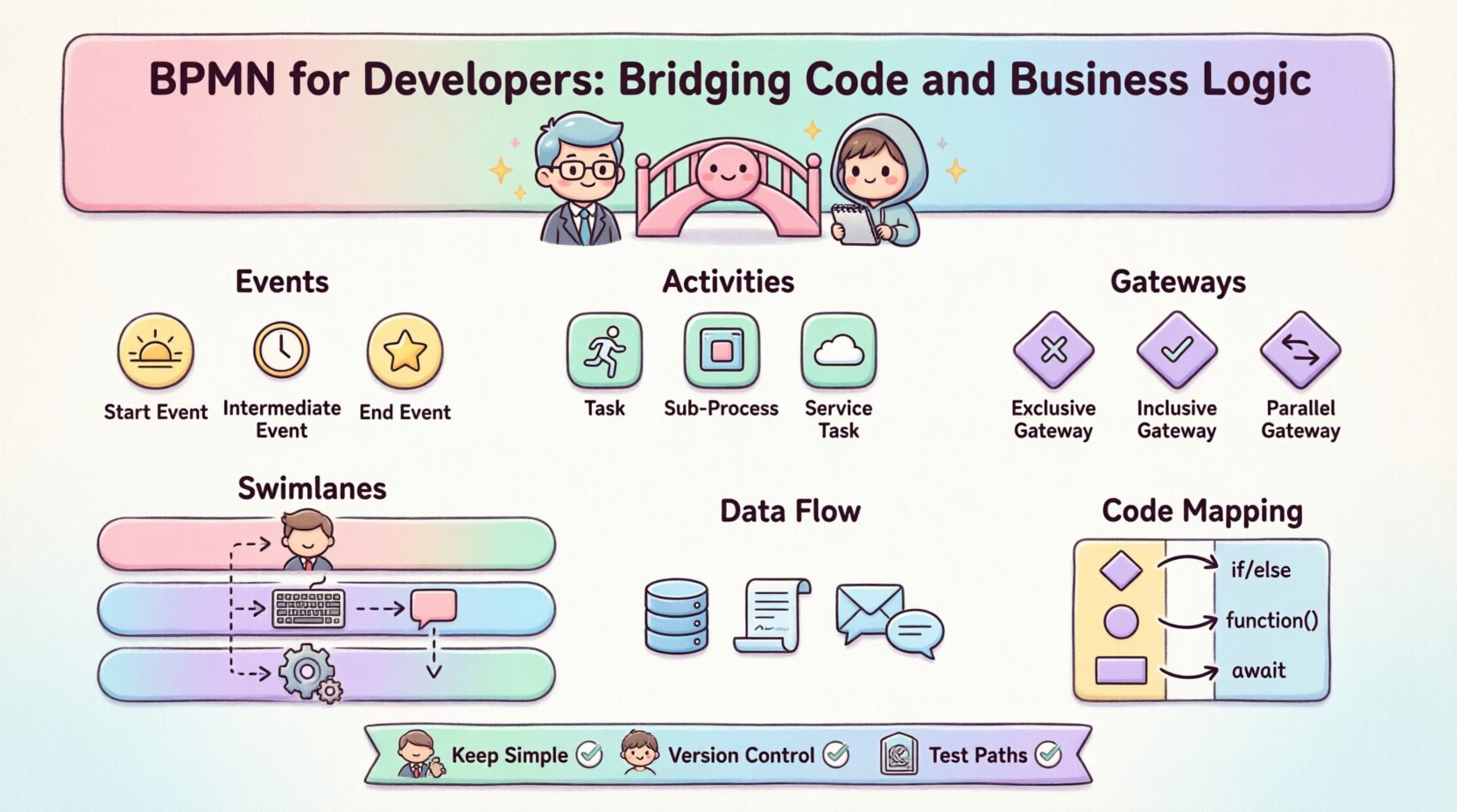
1. Events ⏱️
Events are the occurrences that affect the flow of the process. They are represented by circles. In a coding context, these often map to triggers, callbacks, or API calls.
- Start Events: Initiate the process. In code, this is the entry point of a function or the trigger for a microservice.
- Intermediate Events: Occur during the process. These might represent waiting for a message, a timer expiration, or an error condition.
- End Events: Terminate the process. This corresponds to the return statement or the completion of a transaction.
2. Activities 🏃
Activities represent work performed within the process. They are the core functional units.
- Tasks: Atomic units of work. A single task might map to a specific API call or a database transaction.
- Subprocesses: A complex activity broken down into a lower-level process. This encourages modularity and reuse in the codebase.
- Service Tasks: Specifically denote interactions with external systems. This is crucial for developers defining integration points.
3. Gateways 🔀
Gateways control the divergence and convergence of paths. They determine which path the process takes next based on conditions.
- Exclusive Gateways: Decide between one or more paths. This maps directly to an
if-elseorswitchstatement in code. - Inclusive Gateways: Allow multiple paths to be taken simultaneously if conditions are met.
- Parallel Gateways: Split the flow into multiple concurrent threads, similar to parallel processing or async tasks.
Swimlanes and Pools: Defining Responsibility 🏊
One of the most powerful features of BPMN is the ability to organize processes by who performs the work. This is achieved through Pools and Swimlanes.
- Pools: Represent distinct entities or systems. A pool can represent the entire application, a specific microservice, or an external partner system.
- Swimlanes: Divide a pool to show the division of responsibility. A swimlane might represent a specific user role, a department, or a specific service within the architecture.
For developers, swimlanes are critical for defining boundaries. They clarify which service or component is responsible for a specific task. This helps in designing service-oriented architectures where each service has a clear domain ownership. By visualizing the handoff points between swimlanes, teams can identify potential integration bottlenecks before writing a single line of code.
Data Flow and Objects 💾
Processes are not just about flow; they are about data. BPMN includes Data Objects to represent the information being processed. Understanding data flow is essential for backend development.
- Data Stores: Indicate persistence. This maps to database schemas or file systems.
- Data Objects: Represent information passing through the process. These correspond to data structures or DTOs (Data Transfer Objects) in the code.
- Message Flow: Shows the communication between pools. This is vital for understanding event-driven architectures.
When developers define data objects in a diagram, they implicitly define the schema required for the application. This encourages a data-first approach to development, ensuring that the data model supports the process logic.
Mapping Diagrams to Code Architecture 🧩
The transition from a visual model to executable code requires a systematic approach. Developers often struggle with how to translate a complex diagram into a maintainable codebase. Here is how the mapping typically works.
Orchestration vs. Choreography
In modern distributed systems, two patterns emerge from process modeling:
- Orchestration: A central controller manages the flow. This is common when using a workflow engine. The engine dictates the order of operations.
- Choreography: Participants coordinate themselves without a central controller. This relies on events and message exchanges. Developers must ensure that the state is consistent across services.
State Management
Processes often require long-running states. A standard function call cannot wait for days. BPMN handles this through the concept of waiting for events.
- Long-Running Processes: The state of the process must be persisted to a database. When a timer event fires, the system retrieves the state and resumes execution.
- Sagas: In microservices, a saga pattern manages distributed transactions. BPMN diagrams can visualize the compensation logic required if a step fails.
Exception Handling and Compensation ⚠️
Software systems fail. Business processes fail. A robust BPMN model must account for these failures explicitly.
- Error Events: Catch errors that occur during a task. This allows the process to take a specific error-handling path rather than crashing.
- Compensation: If a process completes successfully but a later step fails, compensation logic reverses the effects of previous steps. This is critical for financial or inventory transactions.
- Boundary Events: Attach events to the side of a task to handle exceptions locally without altering the main flow.
Implementing compensation logic is often the hardest part of development. By defining it in the diagram, developers know exactly what rollback procedures are required for each service involved.
Performance and Scalability Considerations 🚀
High volume processes require careful modeling. A diagram that works for a few transactions may fail under load.
- Bottleneck Analysis: Visualizing the flow helps identify where tasks queue up. If a human task sits in a swimlane for a long time, the system waits. If a service task is slow, the thread pool fills up.
- Concurrency: Parallel gateways create multiple instances of a task. Developers must ensure the underlying infrastructure can handle this concurrency.
- Batching: Instead of processing one item at a time, processes can be modeled to handle batches. This improves throughput.
Common Pitfalls to Avoid 🚫
While BPMN is powerful, misuse can lead to overly complex models that are hard to maintain.
- Over-Modeling: Do not model every single edge case in the diagram. Focus on the happy path and major exceptions. Too much detail obscures the logic.
- Spaghetti Logic: Avoid connecting too many gateways in a single path. If a path becomes unreadable, refactor the process into subprocesses.
- Ignoring Data: A process without data is just a flow. Ensure data objects are defined for every task to clarify inputs and outputs.
- Hardcoding Logic: Do not put complex business rules inside the task code that should be in the gateway conditions. Keep the diagram clean and the code focused.
Integrating into Development Workflows 🔗
BPMN should not exist in a vacuum. It needs to be part of the Continuous Integration and Continuous Deployment (CI/CD) pipeline.
- Version Control: Process definitions should be stored in version control alongside source code. This ensures traceability between code changes and process changes.
- Validation: Before deployment, the process model should be validated for syntax errors and logical loops. Automated testing tools can check for deadlocks or unreachable paths.
- Documentation: The diagram serves as the single source of truth. When a developer updates code, they must update the diagram to reflect the change.
Maintenance and Versioning 🔄
Business requirements change. The code must evolve to match. Managing versioning of process models is distinct from versioning code.
- Backward Compatibility: Changing a process definition can break running instances. Developers must design migration strategies for old instances.
- Parallel Runs: Sometimes it is necessary to run two versions of a process simultaneously during a transition period.
- Deprecation: Old process versions must be archived and monitored to ensure no new instances start using deprecated logic.
Table: BPMN Elements vs. Code Concepts 📊
The following table provides a quick reference for mapping standard BPMN elements to common programming concepts.
| BPMN Element | Description | Code Equivalent | System Concept |
|---|---|---|---|
| Start Event | Initiates the flow | Function Entry / Trigger | API Endpoint |
| End Event | Terminates the flow | Return Statement | Transaction Commit |
| Task | Atomic work unit | Method / Function | Service Call |
| Exclusive Gateway | Decision point | If / Else / Switch | Conditional Logic |
| Parallel Gateway | Split flow | Async / Parallel Thread | Concurrent Execution |
| Message Flow | Communication | Message Queue / Event | Inter-service Comms |
| Subprocess | Group of tasks | Module / Class | Encapsulation |
| Error Event | Exception handling | Catch Block | Error Handling |
Collaboration Between Teams 🤝
The true power of BPMN is realized when business analysts and developers work from the same model. This reduces the translation layer where errors typically occur.
- Shared Vocabulary: Both parties agree on the meaning of shapes and flows. A “Gateway” means the same thing to the analyst and the engineer.
- Early Validation: Business logic can be validated before development begins. This saves time by preventing the development of features that do not align with requirements.
- Feedback Loops: When a developer encounters a technical constraint, they can update the diagram to reflect it. The business analyst sees the impact immediately.
Future Trends in Process Modeling 🔮
The field of process modeling is evolving alongside technology.
- Low-Code Integration: Process models are increasingly used to drive low-code platforms. Developers build the engine, and the model defines the logic.
- AI Assistance: AI tools can suggest optimizations for process flows or automatically generate code stubs from diagrams.
- Real-time Monitoring: Process models are now linked to runtime analytics. Developers can see where processes get stuck in production and update the model accordingly.
Technical Implementation Guidelines 🛠️
To implement BPMN effectively, follow these technical guidelines.
- Keep Diagrams Simple: Use subprocesses to hide complexity. A diagram should not require scrolling to understand.
- Use Clear Naming: Labels on tasks and gateways should be descriptive. Avoid abbreviations that require a legend to understand.
- Define Data Contracts: Ensure that data objects are typed. This prevents runtime errors caused by missing fields.
- Test Logic Paths: Write unit tests for every branch created by a gateway. Coverage is key.
- Document Assumptions: If a process relies on external timing or specific data states, document this in the diagram notes.
Conclusion on Process Modeling 🏁
Adopting BPMN as a developer does not mean becoming a business analyst. It means gaining the ability to read and write the language of business logic. This skill reduces friction between teams and ensures that the code delivered matches the intended business value. By treating process models as executable specifications, development teams can build systems that are more robust, maintainable, and aligned with organizational goals. The investment in learning these standards pays off in reduced rework and clearer communication across the organization.
Ultimately, the goal is to create software that works as intended. BPMN provides the blueprint for that intention. By integrating these practices into the development lifecycle, teams can ensure that their technical solutions are built on a solid foundation of verified logic.
This post is also available in Deutsch, Español, فارسی, Français, English, Bahasa Indonesia, 日本語, Polski, Portuguese, Ру́сский, Việt Nam, 简体中文 and 繁體中文.