


Software development relies heavily on clear communication between stakeholders, business analysts, and engineering teams. The Business Process Model and Notation (BPMN) standard serves as a universal language for describing workflows. However, even when teams adopt BPMN, errors in modeling often lead to significant friction during the implementation phase. These mistakes are not merely cosmetic; they create ambiguity that propagates through the architecture, testing, and deployment stages.
This guide examines five specific modeling errors that frequently disrupt project timelines. By understanding the technical implications of these pitfalls, teams can ensure their process diagrams accurately reflect the intended system behavior without requiring constant rework.

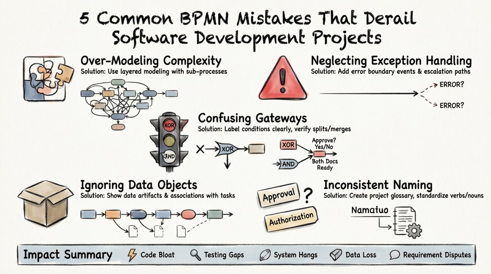
1. Over-Modeling Complexity with Excessive Detail 🧩
One of the most prevalent issues in BPMN modeling is the attempt to capture every single micro-interaction within a process diagram. While thoroughness is a virtue, excessive granularity often obscures the actual flow of logic. When a diagram becomes too dense, it loses its value as a communication tool.
The Technical Impact
- Code Bloat: Developers attempting to map a hyper-detailed diagram may implement logic for edge cases that were never intended to be automated. This leads to unnecessary code branches.
- Performance Overhead: Complex decision trees modeled as gateways can result in inefficient execution flows within the runtime engine.
- Maintenance Burden: Changing a minor step in a highly detailed model requires updating numerous connections, increasing the risk of breaking other parts of the process.
Corrective Approach
Adopt a layered modeling strategy. The top-level diagram should show the high-level sequence of events. Detailed logic should be encapsulated in sub-processes. This keeps the main view clean while allowing developers to drill down into specific requirements only when necessary.
- High-Level View: Focus on major milestones and handoffs between departments.
- Sub-Process View: Use expanded sub-processes for complex logic that requires deeper scrutiny.
- Event-Centric: Ensure the model responds to specific events rather than listing every internal system action.
2. Neglecting Exception Handling Paths ⛔
Many models focus exclusively on the “Happy Path”—the sequence of steps where everything proceeds as expected. In reality, software systems must handle failures, timeouts, and invalid inputs. Ignoring these scenarios during the modeling phase creates a false sense of security regarding the system’s robustness.
Why This Derails Projects
When developers encounter a model that lacks exception paths, they must guess how to handle errors. This leads to:
- Hardcoded Error Handling: Engineers implement generic try-catch blocks instead of structured recovery flows defined by business rules.
- Manual Interventions: Users may find that the system halts unexpectedly, requiring manual database fixes or admin overrides.
- Testing Gaps: QA teams lack specific test cases for failure scenarios because the model did not define them.
Implementing Robust Error Flows
Every critical step in a process should have a defined outcome for both success and failure. Use intermediate error events to capture specific failure modes. Ensure that every process has a clear termination point, whether it ends successfully or via an error boundary.
- Boundary Events: Attach error boundary events to tasks to catch exceptions locally.
- Compensation: Define what happens if a transaction must be rolled back. Who gets notified?
- Escalation: Specify thresholds for escalating issues to human operators when automated retries fail.
3. Confusing Exclusive and Parallel Gateways 🚦
Gateways dictate how a process splits or merges. Distinguishing between an Exclusive Gateway (XOR) and a Parallel Gateway (AND) is fundamental. Misusing these elements changes the logic of the entire workflow. An XOR gateway implies a choice where only one path is taken. An AND gateway implies that all paths must be completed.
The Logic Trap
Using an AND gateway where an XOR is required can cause the system to execute duplicate tasks or wait indefinitely for a branch that will never complete. Conversely, using an XOR where an AND is needed can result in data loss if multiple branches are supposed to run concurrently.
Common Scenarios for Confusion
| Gateway Type | Function | Common Misuse |
|---|---|---|
| Exclusive (XOR) | One path out of many | Used when multiple sub-tasks must run simultaneously |
| Parallel (AND) | All paths must complete | Used when only one conditional branch is valid |
| Inclusive (OR) | One or more paths | Often confused with Exclusive regarding data dependencies |
Ensuring Logical Consistency
Before finalizing the diagram, review every gateway to ensure the conditions match the execution intent. If a task requires a specific condition to be met before proceeding, use an Exclusive Gateway with clear labels. If a task triggers independent actions that run concurrently, use a Parallel Gateway.
- Label Conditions: Never leave gateway conditions blank. Explicitly state the boolean logic.
- Verify Merges: Ensure that every split has a corresponding merge. Orphaned paths indicate incomplete modeling.
- Test Logic: Walk through the diagram as if you were the engine executing it. Does the flow match the requirement?
4. Ignoring Data Objects and Information Flow 📦
A process model is not just about actions; it is about the transformation of data. Many diagrams focus entirely on control flow (the sequence of activities) while neglecting data flow (the objects being created, read, or updated). Without this context, developers cannot design the correct database schema or API contracts.
The Development Gap
When data flow is omitted, the development team must infer data structures from the activity names. This leads to:
- Inefficient Queries: Developers may fetch data unnecessarily because the model did not show where data is consumed.
- Data Integrity Issues: If the model does not show where data is validated, that validation might be missed in the code.
- Interface Mismatches: The frontend may expect fields that the backend process does not generate.
Integrating Data into the Model
Use Data Objects to represent the information artifacts used or produced by tasks. Use Data Associations to show how information moves between tasks, gateways, and artifacts.
- Define Artifacts: Clearly label input documents and output reports.
- Show Transitions: Draw lines connecting data objects to the tasks that modify them.
- Specify Types: Indicate if a data object is a temporary variable or a persistent record.
5. Inconsistent Naming Conventions 📝
Clarity is the currency of modeling. If the diagram uses “Approval” in one section and “Authorization” in another for the same concept, confusion is inevitable. Inconsistent terminology makes it difficult for stakeholders to trust the model and for developers to translate it into code.
The Cost of Ambiguity
When terms are used interchangeably, requirements gathering sessions become debates about definitions rather than functionality. This stalls progress and increases the likelihood of scope creep as teams try to cover all possible interpretations.
Establishing a Glossary
Create a shared glossary for the project. This document defines exactly what each term means within the context of the system. Ensure that the BPMN model adheres strictly to this glossary.
- Standardize Verbs: Use action-oriented labels for tasks (e.g., “Process Order” instead of “Order”).
- Standardize Nouns: Ensure data objects use consistent naming (e.g., “Customer” vs “Client”).
- Review Labels: Before publishing a model, run a text search for synonyms to ensure consistency.
Impact Analysis of Modeling Errors
Understanding the theoretical errors is one thing; understanding the tangible cost of these errors is another. The table below summarizes how specific modeling mistakes translate into project risks.
| Modeling Mistake | Phase Affected | Potential Consequence |
|---|---|---|
| Over-Modeling | Development | Increased technical debt and slower deployment cycles |
| No Exception Paths | Testing & QA | High volume of production incidents and user complaints |
| Gateway Confusion | Architecture | System hangs or infinite loops in the runtime engine |
| Missing Data Flow | Database Design | Incomplete schemas and data loss during transactions |
| Inconsistent Naming | Stakeholder Review | Requirement disputes and delayed sign-off |
Strategic Implementation of BPMN
To mitigate these risks, organizations should treat BPMN not as a documentation exercise but as a design specification. The model should be treated with the same rigor as source code. Version control, peer reviews, and validation against business rules are essential.
Best Practices for Validation
- Walkthroughs: Conduct formal walkthroughs with both business users and developers. Business users verify the logic; developers verify the feasibility.
- Executable Modeling: Where possible, use executable models. If the process engine can run the diagram, it proves the logic is sound before a single line of custom code is written.
- Traceability: Link BPMN elements directly to user stories or requirement documents. This ensures every step in the diagram has a business justification.
Ensuring Long-Term Maintainability
Software projects evolve. Processes change. A model that works today may be obsolete in six months. To prevent technical debt from accumulating, the modeling standards must be sustainable.
- Keep it Simple: A diagram that is easy to understand is easier to change.
- Modularize: Break large processes into smaller, reusable sub-processes.
- Document Assumptions: If a decision was made based on a specific constraint, document it next to the relevant task.
- Regular Audits: Periodically review models against the current system state to ensure they have not drifted from reality.
Conclusion
Adopting Business Process Model and Notation is a strategic advantage, but only when executed correctly. The five mistakes outlined here—over-complication, missing exceptions, gateway confusion, data neglect, and naming inconsistency—are common pitfalls that can stall development efforts. By addressing these areas with discipline and clarity, teams can build software that aligns precisely with business needs.
The goal is not just to draw diagrams, but to create a blueprint that developers can trust. When the model is accurate, the resulting software is robust, maintainable, and fit for purpose. Prioritize precision over speed in the modeling phase to save significant time and resources during implementation.
This post is also available in Deutsch, Español, فارسی, Français, English, Bahasa Indonesia, 日本語, Polski, Portuguese, Ру́сский, Việt Nam, 简体中文 and 繁體中文.