


Business Process Model and Notation (BPMN) serves as the standard for business process modeling. It provides a graphical representation that bridges the gap between process design and implementation. Version 2.0 of this specification introduced significant enhancements to the visual logic and semantic capabilities of the notation. Understanding these components is essential for creating models that are executable, readable, and accurate.
This guide explores the core elements of BPMN 2.0. It covers flow objects, connecting objects, swimlanes, artifacts, and the specific logic governing decision points. By mastering the structure and meaning of these symbols, organizations can ensure clarity in their operational workflows.
1. The Core Philosophy of BPMN Visuals ⚙️
At its heart, BPMN is about communication. It allows stakeholders, from business analysts to developers, to view the same process from a unified perspective. The notation is designed to be intuitive, using shapes that convey meaning without requiring extensive training.
- Standardization: The Object Management Group (OMG) maintains the standard to ensure consistency across different platforms.
- Visual Semantics: Every shape has a specific definition regarding what it does and how it behaves.
- Executable Logic: Beyond drawing, BPMN 2.0 allows for the execution of processes by defining precise entry and exit conditions.
When constructing a diagram, the goal is to represent the flow of work accurately. This involves understanding the interaction between different types of nodes and how data moves through the system.
2. Flow Objects: The Engine of the Process 🔄
Flow objects are the fundamental building blocks of any BPMN diagram. They define the actual work being performed and the path the process takes. There are three primary categories of flow objects: Events, Activities, and Gateways.
2.1 Events 🏁
Events represent something that happens during the course of a process. They are depicted as circles and affect the flow of the process. Events are categorized by their position in the process: start, intermediate, or end.
- Start Events: These trigger the process. They are empty circles by default but can have icons to denote specific triggers (e.g., a message icon or a clock).
- Intermediate Events: These occur during the process. They can pause the flow (e.g., waiting for a response) or pass information along.
- End Events: These mark the termination of the process. They indicate that the work is complete.
Each event type has sub-types that define the nature of the occurrence. For example, an error event signifies a failure condition, while a message event signifies communication with an external entity.
2.2 Activities 🛠️
Activities represent work that is performed within the process. They are depicted as rounded rectangles. The level of detail in an activity can vary significantly.
- Task: The smallest unit of work. It cannot be decomposed further within the diagram.
- Sub-Process: A complex activity that can be broken down into a separate, detailed diagram. This allows for abstraction and modularity.
- Call Activity: References a reusable process definition from another diagram.
Activities can be manual, automated, or user-driven. The notation allows for the inclusion of data inputs and outputs to specify what information is required to complete the work.
2.3 Gateways 🚦
Gateways control the divergence and convergence of the process flow. They determine whether the path splits, merges, or waits for specific conditions. Gateways are represented by diamonds.
The logic within a gateway dictates the behavior of the process path. Common types include:
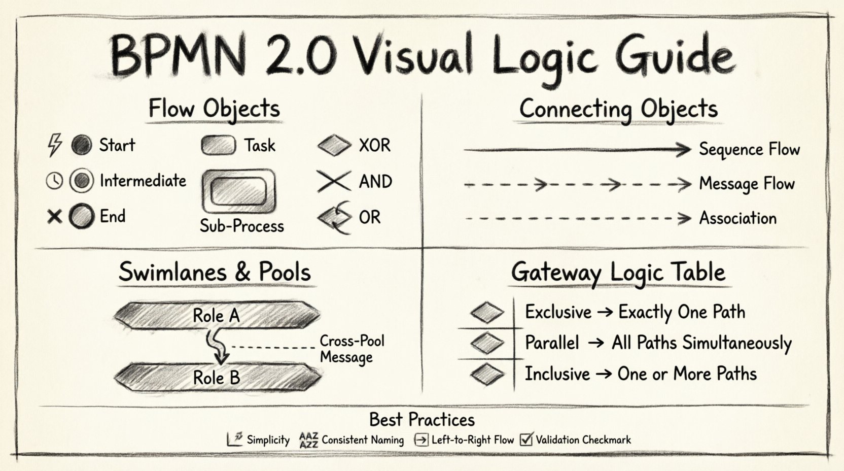
- Exclusive Gateway (XOR): Only one outgoing path is taken. This is used for decisions where only one outcome is possible.
- Inclusive Gateway (OR): One or more outgoing paths may be taken based on conditions.
- Parallel Gateway (AND): All outgoing paths are taken simultaneously. This splits the process into parallel threads.
- Event-Based Gateway: Waits for one of several events to occur. Only the path corresponding to the first event to trigger is taken.
Understanding the distinction between these gateways is crucial for modeling complex logic accurately.
3. Connecting Objects: Linking the Elements 🔗
Connecting objects define the relationships and the sequence between flow objects. They provide the context for how one element leads to the next.
3.1 Sequence Flow ➡️
Sequence flow represents the order of activities in a single process. It is depicted as a solid line with an arrow. It indicates that one element happens immediately after another within the same context.
- It connects flow objects within the same pool.
- It cannot cross pool boundaries.
- It carries the default flow of control.
3.2 Message Flow 💬
Message flow represents the flow of information between different participants. It is depicted as a dashed line with an open arrow head.
- It connects elements across different pools or lanes.
- It signifies communication between separate entities.
- It does not carry process logic, only data or signals.
3.3 Association 📎
An association connects a flow object to a text annotation or data object. It helps clarify the meaning of a specific element without affecting the flow logic.
- It is a dashed line.
- It can be used to link data to an activity.
- It provides context or explanation.
4. Swimlanes and Pools: Organizing Responsibility 🏊♂️
Swimlanes provide a way to organize activities by participant, role, or system. They help clarify who is responsible for each step in the process.
4.1 Pools 🏊
A pool represents a participant in a process. It can be a single organization, a department, or a specific system. A pool can contain multiple lanes.
- Each pool is an independent context.
- Message flows are required to connect elements between different pools.
- Multiple pools indicate interactions between different entities.
4.2 Lanes 🛤️
Lanes divide a pool into sub-categories. They are used to group activities by specific roles, departments, or systems within the same organization.
- They improve readability by grouping related tasks.
- They clarify handoffs between different teams.
- They can be nested to show hierarchical structures.
When modeling interactions, placing the correct activity in the correct lane is vital. It ensures that the responsibility matrix is clear and that the flow of work respects organizational boundaries.
5. Artifacts and Annotations 📝
Artifacts provide additional information about the process without affecting the execution logic. They are used to add context, data definitions, or grouping.
5.1 Data Objects 📄
Data objects represent the information consumed or produced by an activity. They are depicted as a page with a folded corner.
- They show the input or output of a task.
- They are linked via associations.
- They help define the data requirements for the process.
5.2 Groups 📦
Groups are used to visually group activities together. They are represented by a rectangle with a label at the top.
- They do not affect the flow of the process.
- They are used for categorization or documentation.
- They help manage complex diagrams by clustering related elements.
5.3 Text Annotations 📌
Text annotations allow the modeler to add explanatory notes to specific elements. They appear as a rectangle with a folded corner.
- They provide detailed descriptions.
- They can be linked to specific flow objects via associations.
- They are useful for compliance documentation.
6. Gateway Logic and Decision Points 🧠
The logic within gateways determines the path of execution. Misinterpreting gateway logic is a common source of error in process modeling. Below is a detailed breakdown of the most common gateway types.
| Gateway Type | Symbol | Behavior | Use Case |
|---|---|---|---|
| Exclusive (XOR) | ⛔ | One path only | Approval decisions (Yes/No) |
| Inclusive (OR) | 🔀 | One or more paths | Multi-channel notifications |
| Parallel (AND) | ➕ | All paths simultaneously | Split work for parallel execution |
| Complex | ⚙️ | Custom logic | Non-standard decision trees |
When using Exclusive Gateways, conditions must be mutually exclusive. If a path is not taken, the process does not proceed down that route. In contrast, Parallel Gateways do not check conditions; they simply split the flow to ensure all subsequent tasks are executed.
Convergence is equally important. A Parallel Gateway that splits the flow must have a matching Parallel Gateway that merges the flow back into a single path. Failure to synchronize parallel threads can lead to deadlocks or orphaned tasks.
7. Event Types and Their Specifics ⏱️
Events are more than just start and stop points. They define the triggers and outcomes of the process. BPMN 2.0 defines specific event types that carry distinct meanings.
7.1 Start Events
- Message: Triggered by receiving a message.
- Timer: Triggered at a specific time or interval.
- Signal: Triggered by an internal signal broadcast.
- Error: Triggered by a system error (rare for start).
7.2 Intermediate Events
These events can interrupt the flow or pass through it.
- Timer: Delays the process until a specific time.
- Message: Waits for an incoming message.
- Signal: Broadcasts or catches a signal.
- Escalation: Handles escalation procedures.
7.3 End Events
- Terminate: Stops the entire process immediately.
- Message: Sends a message upon completion.
- Error: Indicates a failure occurred.
- Escalation: Indicates an escalation occurred.
Selecting the correct event type ensures that the process handles external interactions and internal states correctly. For example, a Timer Start Event is ideal for scheduled batch jobs, whereas a Message Start Event is best for order intake processes.
8. Best Practices for Modeling Clarity ✨
Creating a BPMN diagram is not just about drawing symbols. It is about creating a document that can be understood by all stakeholders. Adhering to best practices ensures the model remains maintainable and useful.
- Keep it Simple: Avoid cluttering the diagram with unnecessary details. Use sub-processes to hide complexity.
- Consistent Naming: Use clear and consistent names for lanes, tasks, and events.
- Logical Flow: Ensure the flow moves from left to right or top to bottom. Avoid crisscrossing lines.
- Validation: Check for deadlocks. Ensure every path leads to an end event.
- Standard Icons: Use the standard shapes provided by the specification to avoid confusion.
When a diagram becomes too complex, it loses its value. Breaking down a large process into a hierarchy of diagrams is often the most effective strategy. This allows stakeholders to view the high-level overview without getting lost in the details.
9. Data and Process Interaction 📊
Processes do not exist in a vacuum. They manipulate data. Understanding how data objects interact with activities is key to defining the operational requirements.
- Input Data: What information is needed before an activity can start?
- Output Data: What information is produced after the activity completes?
- Data Stores: Where is information persisted? While BPMN primarily focuses on flow, data stores are often implied or linked via associations.
By clearly defining data inputs and outputs, the model becomes a blueprint for system integration. It tells developers exactly what data fields are required and what should be returned.
10. Handling Exceptions and Errors ⚠️
Real-world processes are rarely perfect. Exceptions and errors must be accounted for in the model. BPMN provides specific mechanisms to handle these scenarios.
- Error Events: These can be attached to activities to catch runtime errors.
- Compensation: Defines actions to undo work if a process fails.
- Boundary Events: Events attached to the edge of an activity. They allow for exception handling without interrupting the main flow logic.
Using boundary events effectively allows the process to continue even if an error occurs, provided the error is handled appropriately. This is crucial for building resilient business processes.
11. Implementation Considerations 💻
While the notation is visual, it is often intended for execution. The model serves as a specification for workflow engines. Therefore, the logic must be precise.
- Executable Syntax: Ensure all gateways and events have defined conditions.
- Variable Mapping: Define how process variables map to data objects.
- Service Integration: Identify where external services are called within the flow.
A well-defined BPMN 2.0 model reduces ambiguity during implementation. It provides a single source of truth for both business requirements and technical specifications.
12. Summary of Key Elements 🏷️
To ensure a comprehensive understanding, here is a quick recap of the primary components discussed.
- Flow Objects: Events, Activities, Gateways.
- Connecting Objects: Sequence Flow, Message Flow, Association.
- Swimlanes: Pools and Lanes for organization.
- Artifacts: Data Objects, Groups, Annotations.
- Logic: Gateways determine path, Events determine triggers.
Mastery of these elements allows for the creation of robust process models. Whether for analysis, design, or execution, the clarity of the notation directly impacts the success of the initiative.
The standard continues to evolve, but the core principles of BPMN 2.0 remain stable. By focusing on the logic and semantics of the components, organizations can achieve better alignment between business goals and operational execution.
Effective modeling requires attention to detail. Every line, shape, and label contributes to the overall meaning of the process. Taking the time to structure the diagram correctly pays dividends in clarity and efficiency.
This post is also available in Deutsch, Español, فارسی, Français, English, Bahasa Indonesia, 日本語, Polski, Portuguese, Ру́сский, Việt Nam, 简体中文 and 繁體中文.