


The UML Activity Diagram is fundamentally a flowchart that models the sequential and concurrent steps, or activities, of a process. It is used to describe the dynamic aspects of a system, focusing on the flow of control from one activity to the next.
This diagram is invaluable for modeling business processes, defining workflows across different components, and documenting the internal logic of a system or method.
Core Elements of Activity Flow
An Activity Diagram is built upon nodes (representing steps) and edges (representing the flow of control).
A. Activity and Action Nodes
These represent a single step or task performed in the process.
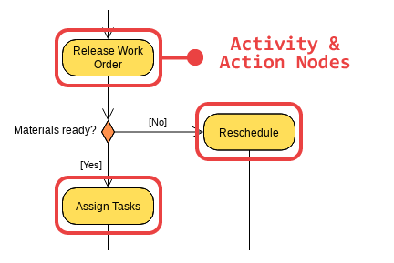
- Notation: A rounded rectangle.
- Action Node: Represents an atomic, non-interruptible step (e.g., Check Inventory).
- Activity Node: Represents a high-level goal that can be broken down further into sub-activities (e.g., Fulfill Order).
- Purpose: To define the work that needs to be performed.
B. Control Flow (Edges)
The control flow is the arrow connecting two nodes, showing the transition from one action to the next.
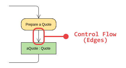
- Notation: A solid arrow.
- Purpose: Indicates the sequence of execution.
C. Start and End Nodes
Every diagram must have a single starting point and one or more ending points.
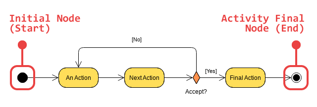
- Initial Node (Start):
- Notation: A solid, filled circle.
- Purpose: The entry point for the control flow.
- Activity Final Node (End):
- Notation: A solid circle surrounded by a larger hollow circle.
- Purpose: Indicates the completion of all flows in the activity.
- Flow Final Node:
- Notation: A circle with an ‘X’ inside.
- Purpose: Indicates the end of a specific path (flow) but does not necessarily terminate the overall activity.
Modeling Decision and Branching Logic
Activity Diagrams use specific nodes to handle conditional logic, much like if-else or switch statements in code.
A. Decision and Merge Nodes
These nodes are used to model conditional branching and the subsequent rejoining of those paths.
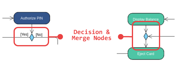
- Decision Node:
- Notation: A diamond shape.
- Usage: A single incoming flow and multiple outgoing flows. Each outgoing flow must have a Guard Condition (a condition in square brackets, e.g.,
[Inventory > 0]) that determines which path is taken.
- Merge Node:
- Notation: A diamond shape.
- Usage: Multiple incoming flows and a single outgoing flow. It simply represents the point where different branches rejoin, signifying that any of the incoming branches can lead to the next step. It does not synchronize concurrent flows.
Modeling Concurrency and Synchronization
Unlike flowcharts which are typically sequential, Activity Diagrams excel at showing parallel execution using Synchronization Bars.
A. Fork and Join Nodes
These nodes are used to split a single flow of control into multiple, concurrent flows, and later, to wait for those concurrent flows to complete.

- Fork Node:
- Notation: A thick horizontal or vertical bar.
- Usage: A single incoming flow and multiple outgoing flows. All outgoing flows start executing concurrently (in parallel) from this point.
- Join Node:
- Notation: A thick horizontal or vertical bar.
- Usage: Multiple incoming flows and a single outgoing flow. The outgoing flow cannot begin until all incoming concurrent flows have completed (synchronization).
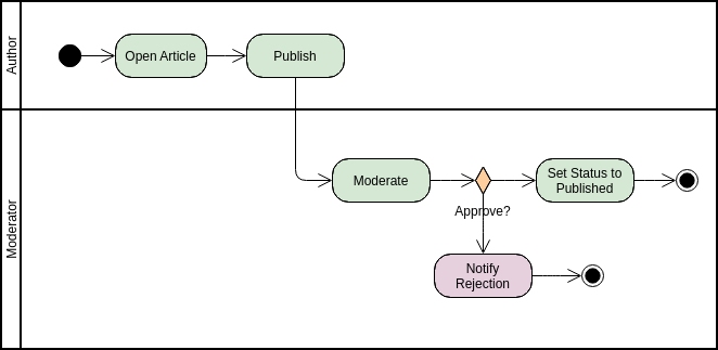
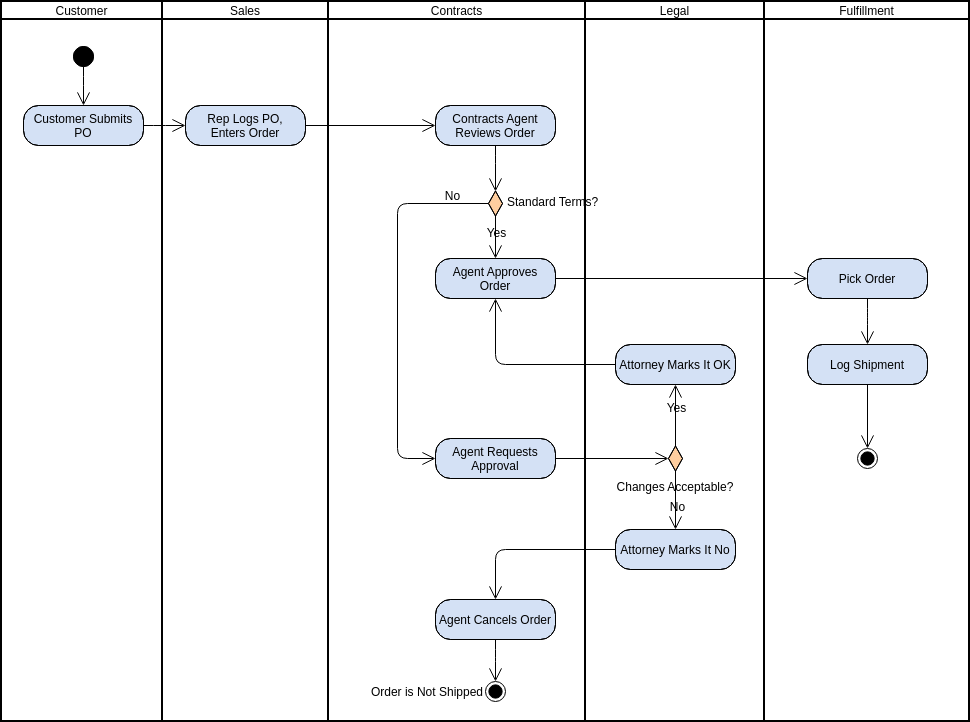
Organizational Elements: Swimlanes
Swimlanes (also called Partitions) are essential for showing which department, component, or Actor is responsible for which activity. They visually divide the diagram into vertical or horizontal zones.
- Notation: Vertical or horizontal parallel lines separating different areas of responsibility.
- Purpose: To group actions by the entity responsible for performing them, providing clear accountability across different organizational units (e.g., “Customer,” “Web System,” “Warehouse”).
Summary of Activity Diagram Best Practices
- Model Flow, Not Objects: Focus on the sequence of steps and the flow of control, not the structural relationships between classes (that’s the Class Diagram’s job).
- Use Swimlanes: Always use swimlanes to clearly delineate who or what is performing each action, especially in cross-functional business processes.
- Label Guards: Ensure that every outgoing flow from a Decision Node is labeled with a clear, mutually exclusive Guard Condition (e.g.,
[A],[B],[Else]). - Synchronize Forks: Every Fork must be balanced by a Join to ensure that subsequent steps wait for all parallel activities to finish.
For a deeper understanding of UML and the ways AI can visualize it, explore our UML resource hub.
This post is also available in Deutsch, Español, فارسی, Français, English, Bahasa Indonesia, 日本語, Polski, Portuguese, Ру́сский, Việt Nam, 简体中文 and 繁體中文.