


The Use Case Diagram is a behavioral diagram within the Unified Modeling Language (UML) that provides a high-level, graphical view of a system’s intended functionality. It defines what the system does by illustrating the relationship between users (Actors) and the functions they perform (Use Cases).

This diagram is crucial during the requirements gathering and analysis phase, as it establishes the boundary and scope of the system from a business perspective.
1. Core Elements of a Use Case Diagram
The Use Case Diagram uses only a few fundamental elements, making it one of the simplest UML diagrams to read and create.
A. The System Boundary
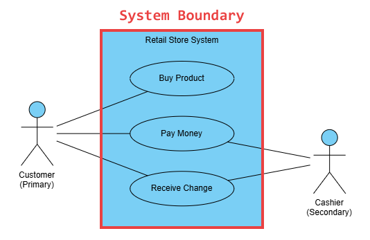
The system boundary is a rectangle that visually defines the scope of the system under consideration. Everything within the box is part of the system; everything outside the box is external.
- Notation: A large rectangle.
- Purpose: To clearly separate the responsibilities of the system from the external entities (Actors) that interact with it.
B. Actors
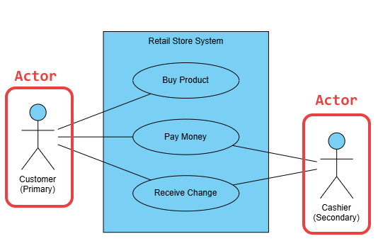
An Actor represents any entity external to the system that interacts with it to achieve a goal. An Actor does not have to be a human being; it can be another system, a hardware device, or even a specific time event.
- Notation: A stick figure labeled with the role name.
- Definition: An Actor is a role, not a specific person. For example, “Customer” is an Actor, while “Jane Doe” is an instance of that role.
- Types of Actors:
- Primary Actor: Initiates the interaction to achieve a desired goal (e.g., Customer initiating a purchase).
- Secondary Actor: Provides services to the system (e.g., Payment Gateway).
- Passive Actor: Affected by the Use Case but does not initiate it (e.g., Warehouse System receiving a shipment notification).
C. Use Cases

A Use Case represents a single, complete functional requirement or a set of actions that yields a measurable value to an Actor. They should be phrased as simple, active verbs and nouns.
- Notation: An ellipse placed within the system boundary.
- Examples: Place Order, Login to Account, Process Refund, Generate Report.
- Key Rule: A Use Case must always be initiated by an Actor and must provide a valuable outcome to one or more Actors.
2. Relationships in the Use Case Diagram
Relationships connect Actors to Use Cases and connect Use Cases to each other, defining complexity and flow logic.
A. Communication Association
This is the simplest and most common relationship, indicating that an Actor participates in a Use Case.
- Notation: A solid line connecting an Actor to a Use Case ellipse.
- Purpose: Shows which functions are initiated or used by which roles.
B. Include Relationship (<<include>>)
The include relationship is used when one Use Case always incorporates the functionality of another Use Case. The included Use Case is mandatory for the base Use Case to complete its function.
- Notation: A dashed arrow pointing from the Base Use Case to the Included Use Case, labeled with
<<include>>. - Usage: Used to factor out common behavior from multiple Use Cases.
- Example: Place Order includes Authenticate User.
C. Extend Relationship (<<extend>>)
The extend relationship is used when a specific Use Case (the extending one) adds optional or conditional behavior to another Use Case (the base one).
- Notation: A dashed arrow pointing from the Extending Use Case to the Base Use Case, labeled with
<<extend>>. - Usage: Models alternative, exceptional, or specialized behavior. The extension only happens if a specific condition is met.
- Example: Process Payment is the base Use Case, and Apply Loyalty Discount extends Process Payment under the condition
[if loyalty status is Gold].
- Example: Process Payment is the base Use Case, and Apply Loyalty Discount extends Process Payment under the condition
D. Generalization Relationship (Inheritance)
This relationship indicates that one Actor or one Use Case is a specialized version of another.
- Notation: A solid line with a hollow triangle arrowhead pointing from the specialized element to the more general element.
- Usage:
- Actors: System Administrator is a generalization of Registered User.
- Use Cases: Pay by Credit Card is a generalization of Process Payment.
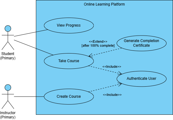
3. Step-by-Step Example: An Online Learning Platform
Imagine modeling the core functionality of an online learning platform.
| Element | Type | Description |
|---|---|---|
| Student | Actor | Primary user role. |
| Instructor | Actor | Creates and manages content. |
| Take Course | Use Case | The primary function of the student. |
| View Progress | Use Case | A valuable function for the student. |
| Authenticate User | Use Case | Common, mandatory step for both actors. |
| Create Course | Use Case | Primary function of the instructor. |
| Generate Completion Certificate | Use Case | Optional function that extends Take Course. |
Modeling the Flow
- System Boundary: Draw a large box encompassing all Use Cases.
- Lifelines: Place Student and Instructor actors outside the box.
- Communication: Connect Student to Take Course and View Progress. Connect Instructor to Create Course.
- Include: Take Course and Create Course both connect to the Authenticate User Use Case with
<<include>>arrows, as logging in is mandatory for both. - Extend: The Generate Completion Certificate Use Case connects to Take Course with an
<<extend>>arrow, indicating it only happens under the condition[after course is 100% complete].
Summary
The UML Use Case Diagram is a powerful yet simple modeling tool that focuses on functional requirements and the user’s perspective. By clearly defining Actors, Use Cases, and the system boundary, you ensure all stakeholders—from business analysts to developers—have a shared, unambiguous understanding of what the system is designed to do. It serves as the starting point for more detailed behavioral models, such as the Sequence Diagram.
For supplementary details about UML and how AI helps you visualize it, explore our UML resource hub.
This post is also available in Deutsch, Español, فارسی, Français, English, Bahasa Indonesia, 日本語, Polski, Portuguese, Ру́сский, Việt Nam, 简体中文 and 繁體中文.