


The Unified Modeling Language (UML) is the universal blueprint for software systems. However, a common mistake is treating UML diagrams as simple pictures—something you can quickly sketch in a general drawing program or a presentation slide.
While those tools suffice for napkin sketches, they fundamentally fail when the design needs to move from concept to code. Modern software development, defined by high complexity and rapid iteration, demands dedicated UML modeling software. These tools are not just for drawing; they are for engineering.
Here is a comprehensive look at why general drawing applications fall short and what dedicated UML tools provide to bridge the critical gap between design and implementation.
1. The Critical Flaw of General Drawing Tools
Tools like general purpose charting applications or presentation software are designed for static visual communication. When used for UML, they suffer from three fatal flaws that cause “documentation drift”:
- Lack of Semantic Validation: In a drawing tool, a line is just a line. In a dedicated UML tool, a line between two classes is an association or inheritance relationship. The tool validates the line’s connection, multiplicity, and direction against UML standards. General tools allow you to draw illegal diagrams that might look right but convey incorrect meaning.
- Static Output: Diagrams in drawing programs are final images (PNG, SVG). They are disconnected from the source code and cannot be easily queried, manipulated, or used to generate documentation.
2. Mandatory Features of Professional UML Modeling Tools
Dedicated tools transform diagrams from static artifacts into dynamic, functional elements of the development lifecycle.
A. Standardization and Precision
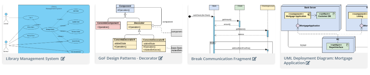
A professional UML tool enforces the rules of the Object Management Group (OMG) standard. This means every symbol, connector, and notation is used correctly. This precision is essential for:
- Ambiguity Reduction: Ensuring all team members, regardless of background, interpret the design exactly the same way.
- Modeling Complex Relationships: Tools handle intricate details like association classes, ports, and composition relationships that would be tedious or impossible to manage manually.
B. Code Engineering (Forward and Reverse)
This is the most powerful differentiator. Dedicated tools manage the relationship between your model and your source code.
- Forward Engineering (Model-to-Code): The tool can automatically generate skeletal source code (classes, methods, attributes, interfaces) in languages like Java, C#, or Python directly from your Class Diagram. This eliminates repetitive boilerplate coding and ensures the initial code structure perfectly matches the architectural design.
- Reverse Engineering (Code-to-Model): If you inherit a legacy codebase or want to document a rapidly developed system, the tool can read existing source code and automatically generate accurate UML Class Diagrams, Sequence Diagrams (for interaction flow), and Package Diagrams. This keeps documentation evergreen and speeds up developer onboarding.
C. Comprehensive Model Management
Professional tools treat the entire collection of diagrams as a single, unified model, not just a folder of files.
- Traceability: You can click an element in a Deployment Diagram and instantly see its corresponding definition in the Class Diagram and its behavior in the Sequence Diagram. This creates complete system traceability.
- Versioning and Collaboration: Diagrams are stored in a centralized repository, allowing multiple architects and developers to work on the same model concurrently, complete with version history and merging capabilities—just like source code.
3. The Next Frontier: Automation and Conversational Modeling
While traditional dedicated tools offer immense power, the latest generation is integrating Artificial Intelligence to accelerate the process even further.
The emergence of AI-powered features, such as the AI Chatbot, represents the logical next step.
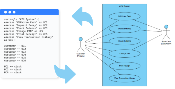
Instead of meticulously drawing or typing complex PlantUML syntax, these tools allow you to describe your system architecture in plain natural language.
- Instant Diagramming: You can type: “Create a sequence diagram for a user resetting their password, including steps for the web server, authentication service, and email microservice.” The AI instantly generates the diagram, already semantically correct.
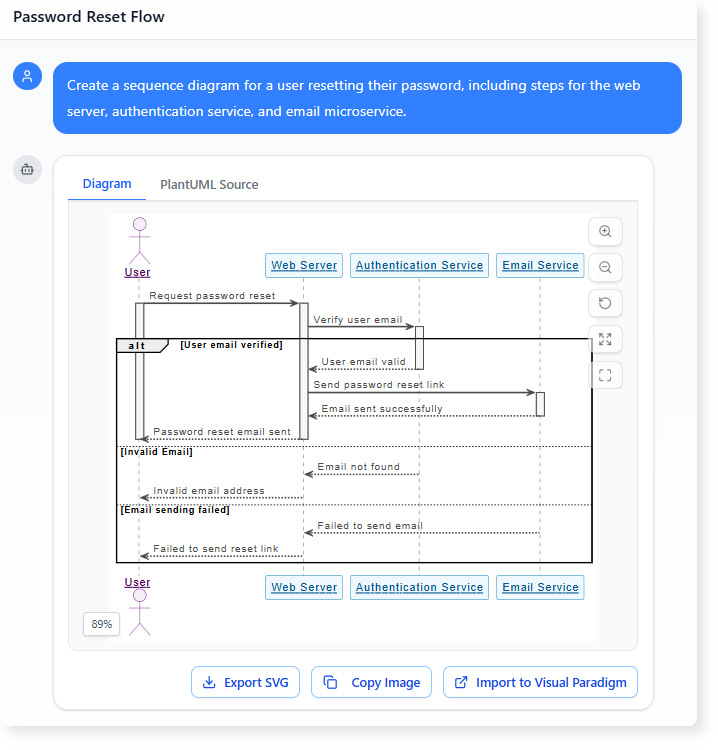
- Conversational Refinement: Refinements become conversational: “Change the email service to be an asynchronous call” or “Rename the User class to Customer.”
- Complexity Management: For systems with hundreds of classes or complex state flows, AI handles the intricate layout and relationship mapping, freeing the architect to focus purely on design strategy.
This AI-driven automation significantly reduces the time cost traditionally associated with maintaining detailed UML documentation, making it a viable and valuable practice even in fast-paced Agile environments.
Conclusion
If your UML diagrams are merely visual aids, you’re missing out on their true power. Dedicated UML diagramming tools are indispensable engineering assets that enforce standards, automate code-model synchronization, and provide a single source of truth for your system’s architecture.
The choice is simple: rely on static images that quickly drift from reality, or embrace a tool that actively keeps your design synchronized with your code. Take action now!
To find out more about UML and the AI tools that visualize it, check our UML resource hub.
This post is also available in Deutsch, Español, فارسی, Français, English, Bahasa Indonesia, 日本語, Polski, Portuguese, Ру́сский, Việt Nam, 简体中文 and 繁體中文.