


A UML use case diagram is the primary form of system/software requirements for a new software program under developed. Use cases specify the expected behavior (what) of a system, and not the exact method of making it happen (how). A complete set of use cases specifies all the different ways to use the system and therefore defines all behavior required of the system bounding the scope of the system.
A key concept of use case modeling is that it helps us design a system from end user’s perspective. It is an effective technique for communicating system behavior in the user’s terms by specifying all externally visible system behavior.
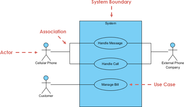
Use Case Diagram at a Glance
A standard form of use case diagram is defined in the Unified Modeling Language as shown in the Use Case Diagram example below:
What is a Use Case?
- A use case is a collection of possible sequences of interactions between the system under discussion and its external actors related to a particular goal.
- Each use case is a complete course of events in the system from a user perspective.
- Use cases once specified can be denoted both textual and visual representation (i.e. use case diagram).
- Use cases are the method favored by the component and object community to specify requirements and indeed to drive the whole software development process.
- Use cases usually stick to fairly major tasks; they do not need to be written for every action the user can take.
Benefits of Use Case Approach
Use cases provide many benefits beyond defining user requirements. Use cases can be used to:
- Use case help to capture the functional requirements of a system.
- Use cases are traceable.
- Use cases can serve as the basis for the estimating, scheduling, and validating effort.
- Use case can evolve at each iteration from a method of capturing requirements, to development guidelines to programmers, to a test case and finally into user documentation.
- Use case alternative paths capture additional behavior that can improve system robustness.
- Use cases have proved to be easily understandable by business users, and so have proven an excellent bridge between software developers and end users.
- Identify business-domain classes and their associates
Actor
- Someone interacts with use case (system function).
- Named by noun.
- Actor plays a role in the business
- Similar to the concept of user, but a user can play different roles
- For example:
- A prof. can be instructor and also researcher
- plays 2 roles with two systems
- Actor triggers use case(s).
- Actor has responsibility toward the system (inputs), and Actor have expectations from the system (outputs).

Use Case
- System function (process — automated or manual)
- Named by verb + Noun (or Noun Phrase).
- i.e. Do something
- Each Actor must be linked to a use case, while some use cases may not be linked to actors.

Communication Link
- The participation of an actor in a use case is shown by connecting a actor to a use case by a solid link.
- Actors may be connected to use cases by associations, indicating that the actor and the use case communicate with one another using messages.

Boundary of system
- The system boundary is potentially the entire system as defined in the requirements document.
- For large and complex systems, each modules may be the system boundary.
- For example, for an ERP system for an organization, each of the modules such as personal, payroll, accounting, etc.
- can form a system boundary for use cases specific to each of these business functions.
- The entire system can span all of these modules depicting the overall system boundary
6 Steps Use Case Analysis
When developing use cases you should start with a functional partition — a listing of the major functional categories of the targeted system. This will help identify what areas need to be focused on.
Step 1 — identify Actors: Identify who is going to be using the system directly. These are the Actors.
- One of the main component of use case development is actors.
- An actor is a specific role played by a system user and represents a category of users that demonstrates similar behaviors when using the system.
- The actors may be people or computer systems.
- A primary actor is one having a goal requiring the assistance of the system.
- A secondary actor is one from which the system needs assistance to satisfy its goal.
- One of the actors is designated as the system under discussion.
- A person can play several roles and thereby represent several actors, such as computer-system operator or end user.
Step 2: Pick one of those Actors.
- To identify a target system’s use case, we identify the system actors.
- A good starting point is to check the system design and identify who it is supposed to help.
Step 3 — Identify Use Cases: Define what that Actor wants to do with the system. Each of these things that the actor wants to do with the system become a Use Case.
- The things that the actors want to do with the system become goals.
- The goal is the end outcome of the actions of the user. There are two types of goals. The first type is a rigid goal.
- This goal must be completely satisfied and describes a target system’s minimum requirement.
- To identify use cases, we can read the requirement specification from an actor’s perspective and carry on discussions with those users who will function as actors.
- By defining everything that every actor will be able to do in interaction with the system, the complete functionality of the system is defined.
Step 4 — Identify the Normal Use Case Scenario: For each of those Use Cases decide on the most usual course when that Actor is using the system. What normally happens.
- A use case has one basic course and several alternative courses.
- The basic course is the simplest course, the one in which a request is delivered without any difficulty.
- There may be alternative courses that describe variants of the basic course and the errors that can occur.
- These are documented as extensions to the use case.
Step 5 — Develop Use Case Description: Describe that basic course in the description for the use case.
- The use scenario is written from the user’s perspective in view in easy to understand language.
- The steps necessary to achieve the identified goal are written out, know as flow of events.
Step 6 — Develop Use Case Alternative Paths: Once you’re happy with the basic course now consider the alternatives and add those as extending use cases.
Alternative Scenarios of a Use Case
A use case also describes how the system should respond when things either do not go right or do go right, but not in the way we described in the main success scenario. We call these situations extensions.
- There are two varieties: exceptions and alternates.
- Exceptions are failure conditions (something went wrong).
- Alternates are simply a different way for things to go right.
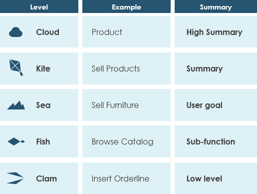
Use Case Levels of Details
Use case granularity refers to the way in which information is organized within use case specifications, and to some extent, the level of detail at which they are written. Achieving the right level of use case granularity eases communication between stakeholders and developers and improves project planning.
Alastair Cockburn in Writing Effective Use Cases gives us an easy way to visualize different levels of goal level by thinking in terms of the sea:
Note that:
- While a use case itself might drill into a lot of detail about every possibility, a use-case diagram often be used for a higher-level view of the system as blueprints.
- It is beneficial to write use cases at a coarser level of granularity with less detail when it’s not required.
I hope you can answer “what is use case diagram” now and can apply use case in your project. If you want to learn more about other UML diagram types, please check the UML guide: Overview of the 14 UML Diagram Types.
References
This post is also available in Deutsch, Español, فارسی, Français, English, Bahasa Indonesia, 日本語, Polski, Portuguese, Ру́сский, Việt Nam, 简体中文 and 繁體中文.