Creating C4 Dynamic Diagrams: Visualizing Runtime Behavior and Interactions with Visual Paradigm’s AI-Powered C4 PlantUML Studio
This article continues the series on supporting/supplementary diagrams in the C4 model. The **Dynamic Diagram** (also known as a runtime or sequence diagram in C4 terminology) is a flexible supporting view that zooms into specific use cases, features, or scenarios, showing how elements (persons, containers, or components) interact at runtime.
Unlike the static structure diagrams (Context/Container/Component), the Dynamic Diagram focuses on behavior over time — answering questions like: “How does a specific feature work?”, “What is the sequence of interactions for a key use case?”, or “How do components collaborate to fulfill a business requirement?” It is typically presented as a sequence diagram, collaboration diagram, or simplified interaction view.
Prerequisites: You must have completed the **Container Diagram** (level 2) and **Component Diagram** (level 3) for the elements you want to explore dynamically — the AI uses these as the foundation for generating accurate runtime flows.
Visual Paradigm’s AI-Powered C4 PlantUML Studio automates this powerful view, intelligently inferring realistic interaction sequences from your problem statement and structural diagrams — making it far superior to manual sequence diagramming in tools like PlantUML, Lucidchart, or draw.io.
Step-by-Step: Generating Your C4 Dynamic Diagram
- Ensure you are in the same project session in Visual Paradigm’s AI-Powered C4 PlantUML Studio (web or desktop).
- Navigate to the tab labeled 6. Dynamic at the top of the interface.
- Select the scope for your dynamic view:
- Use the dropdown menus to choose a specific Container (from your Container Diagram) and/or Component (from your Component Diagram) that you want to focus on.
- This tells the AI which part of the system to animate with runtime interactions.
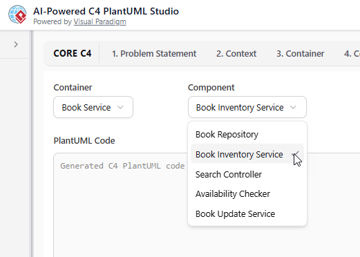
Select the Container and/or Component to focus your runtime/dynamic view
- Click the Generate Diagram button. The AI will create a tailored **Dynamic Diagram** (typically a sequence-style view) showing:
- Step-by-step interactions between elements
- Messages, calls, responses, and data flows
- Actors/users initiating the flow
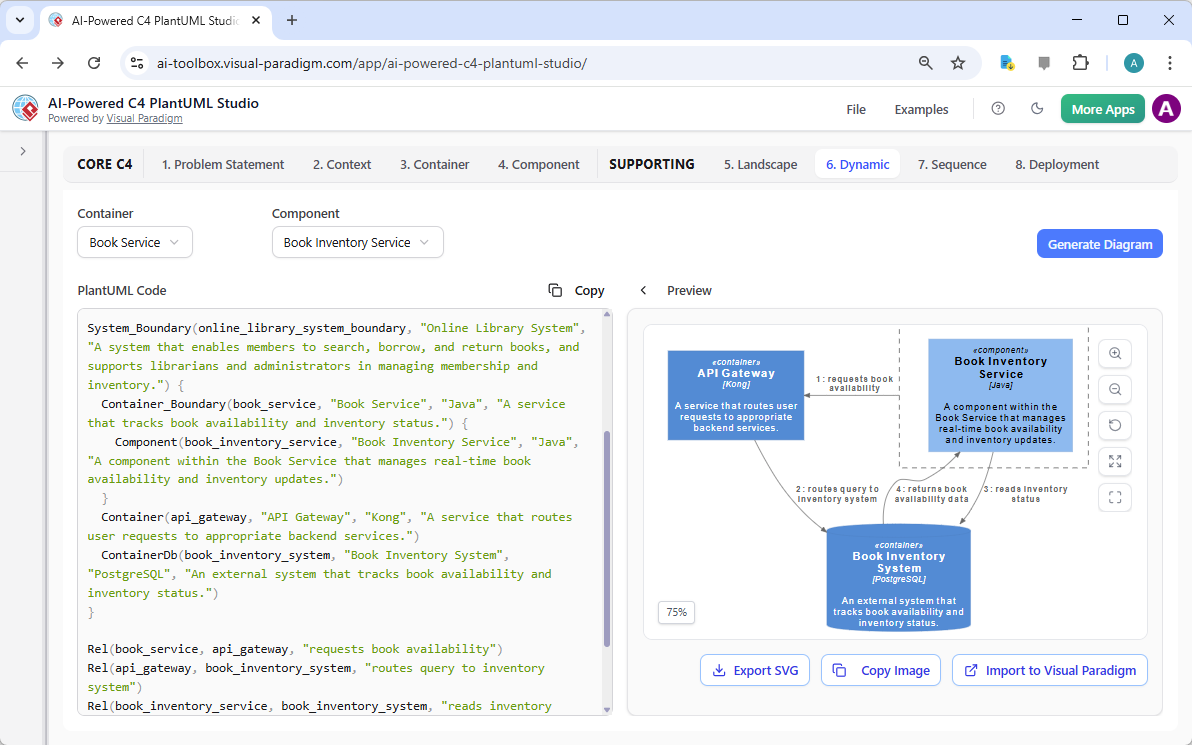
A professional C4 Dynamic Diagram auto-generated with Visual Paradigm’s AI-Powered C4 PlantUML Studio
Pro Tip: After generation, edit the PlantUML code to add timing notes, conditions, loops, or alt fragments for more complex scenarios. The AI maintains consistency with your static diagrams.
Best Practices for Effective Dynamic Diagrams:
- Focus on one key use case or scenario per diagram — avoid overcrowding
- Use clear, numbered steps and meaningful message labels (e.g., “POST /login”, “Validate credentials”)
- Include participants from higher levels (persons/containers) when relevant
- Highlight asynchronous calls, error paths, or parallel processing where needed
- Keep it simple: Use sequence notation for linear flows, collaboration for complex interactions
Visual Paradigm’s AI handles these automatically, ensuring clean, readable, and consistent dynamic views — a huge time-saver for documenting complex behaviors.
What’s Next? Moving to the Final Diagram
Congratulations! You have now successfully created a high-quality **C4 Dynamic Diagram** — bringing your architecture to life with runtime insights.
The final diagram in this series is the **C4 Deployment Diagram**, which maps how your containers and components are physically deployed across infrastructure (servers, cloud environments, networks, etc.).
Continue to the next section to complete your full C4 model with the **Deployment Diagram** using Visual Paradigm’s AI-Powered C4 PlantUML Studio — the ultimate intelligent platform for end-to-end software architecture visualization!